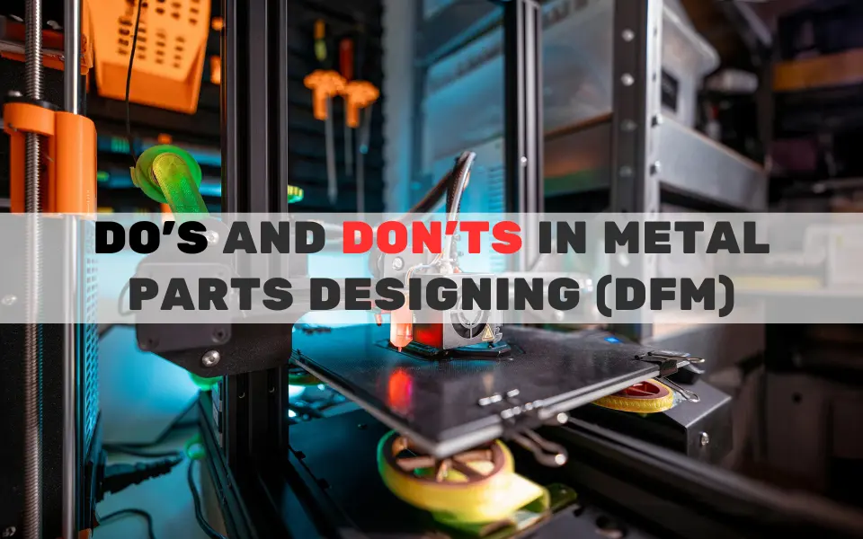
Here’s a comprehensive guide with an embedded infographic—that guides you through the essential do’s and don’ts of metal parts designing (DFM).
A quick overview: Applying DFM principles to your sheet-metal and machined parts ensures lower costs, faster turnaround, and higher quality. You’ll learn how to simplify geometry, select the right materials, leverage standard tooling, and fine-tune tolerances. You’ll also discover common pitfalls—sharp corners, ill-placed features, unrealistic tolerances, and more—that drive up scrap rates and rework. Throughout, citations from leading industry authorities validate each recommendation, so you can confidently optimize your next project for cost, quality, and efficiency.
Why DFM Matters in Metal Fabrication
Design for Manufacturability (DFM) aligns your CAD intent with factory realities to minimize delays, cut costs, and ensure consistent quality across production runs. Early DFM review can reduce part costs by 20–50% by eliminating unnecessary complexity and avoiding last-minute design changes. Whether you’re fabricating automotive brackets, industrial enclosures, or bespoke architectural fittings, integrating DFM saves time and money while boosting reliability.
The Do’s of Metal Parts Designing
1. Simplify Geometry
- Standard Features: Use common bend radii (e.g., 1× material thickness) and hole sizes to match off-the-shelf tooling.
- Symmetry: Design mirror-image parts where possible to improve material nesting and reduce tooling setups by up to 30%.
2. Choose the Right Material
- Application Fit: Match strength, corrosion resistance, and weight requirements to your use case. For example, aluminum 6061 offers lightweight corrosion resistance, while 304 stainless provides superior strength and weldability.
- Availability: Common alloys like 304 SS and 6061-T6 are stocked globally, reducing lead times and unexpected shortages.
3. Design for Standard Tooling
- Press-Brake Limits: Keep inside bend radii at ≥16% of V-die opening—typically 8× material thickness for mild steel up to ½″—to ensure clean bends without springback issues.
- Hole Diameters: Maintain hole sizes ≥ material thickness to prevent punch breakage and burr formation.
4. Add Bend Reliefs
- Prevent Cracking: Include tear-drop or rectangular reliefs at inside corners to avoid material tearing and distortion during bending.
5. Optimize Tolerances
- Critical Only: Apply tight tolerances (±0.1 mm) only on functional surfaces; use standard ±0.5 mm elsewhere to avoid 3–5× cost increases.
- GD&T: Utilize GD&T symbols for clear, unambiguous communication—projected tolerance, datum targets, and surface profile—so shops can interpret requirements consistently.
6. Minimize Welding
- Self-Fixturing: Design tabs, slots, and interlocking features that eliminate the need for fixtures and reduce weld seams by up to 40%.
- Cost & Distortion: Fewer welds mean lower labor costs and minimized heat-induced warping.
7. Consider Surface Finishes Early
- Coating Allowance: Account for powder-coat thickness (60–80 µm or ~0.06–0.08 mm) when dimensioning mating parts to maintain clearances.
- Process Selection: Choose finishes (anodize, plating, dry-film lubricants) that meet functional and aesthetic needs without excessive post-processing.
8. Collaborate with Fabricators
- Early Feedback: Share 3D CAD/STEP files during design reviews. Fabricators can flag tooling limitations, suggest cost-saving tweaks, and validate tolerances before production.
The Don’ts of Metal Parts Designing
1. Avoid Sharp Corners
- Stress Risers: Sharp inside corners concentrate stress and accelerate tool wear. Always use radii ≥ material thickness.
2. Don’t Place Features Near Bends
- Deformation Risk: Keep holes and slots ≥2× material thickness away from bend lines to prevent distortion and cracking.
3. Avoid Overly Thin Walls
- Warping & Crack: Walls <1 mm for steel or <2 mm for aluminum can warp or crack under forming forces.
4. Don’t Mix Processes Unnecessarily
- Complexity Penalty: Combining laser cutting, bending, and welding in a single part without justification drives up setup times and costs.
5. Don’t Overlook Material Grain Direction
- Bend Strength: Bending perpendicular to the grain increases cracking risk and requires higher tonnage. Always orient bend lines parallel to the grain when possible.
6. Avoid Unrealistic Tolerances
- Cost Multiplier: Specifying ±0.1 mm overkill tolerances on non-critical features can inflate part costs by 300–500%.
7. Don’t Skip Burr Removal
- Safety & Fit: Unremoved burrs create injury hazards and can jam assemblies. Always specify deburring to ensure smooth edges and proper fits.
8. Avoid Unmarked Critical Surfaces
- Finish Errors: Failure to label surfaces requiring “anodize,” “no finish,” or “powder coat” can result in mismatched finishes and costly rework.
Key Takeaways
- Simplify: Reduce geometry complexity—standard bends, holes, and symmetries streamline tooling and nesting.
- Standardize: Use common materials (304 SS, 6061 Al) and standard press-brake and punch tooling to cut lead times.
- Communicate: Early collaboration with fabricators prevents surprises, optimizes costs, and ensures your design prints exactly as intended.
By following these do’s and don’ts—reinforced by industry-backed guidelines—you’ll optimize your metal parts for cost, quality, and efficiency from prototype through volume production.