



TL;DR:
- The minimum bend radius is the smallest allowable radius a cable or material can be bent without damage, and it varies by application and standard. Using the most conservative value from datasheets, standards, or tables ensures long-term integrity during installation and use. Proper measurement, documentation, and adherence prevent failure and prolong service life.
The minimum bend radius is the smallest radius a material or cable can be bent without damaging its function or service life. Always use the most conservative applicable value: manufacturer datasheet first, then the governing standard, then a generic table.
Three rules of thumb to keep at your desk: for most general cables, multiply the finished outer diameter (OD) by 8–12 to get a safe long-term installed radius; for fiber optic cable, the Fiber Optic Association recommends 20× OD during installation pulls and 10× OD once installed; for sheet metal, the minimum bend radius is typically expressed as a multiple of material thickness (T), ranging from 0T for soft copper to 3T or more for hard aluminum alloys. When a datasheet and a standard conflict, use whichever gives the larger radius.
Table Of Contents
What Does “minimum Bend Radius” Actually Measure?
Bend radius is not a single measurement convention. Three different values get used depending on the application, and mixing them up is one of the most common sources of acceptance disputes in the field.
Inside radius is the distance from the center of curvature to the inner surface of the bent material. For sheet metal, this is the standard callout on engineering drawings and the value most fabricators quote. For cables, IPC/WHMA-A-620 specifies inspection to the inside curve of the bend, so radius gauges and templates are placed against the inner arc.
Centerline radius (also called the neutral-axis or crown radius) is measured to the midpoint of the cable or material cross-section. It equals the inside radius plus half the cable OD (or half the sheet thickness). Some cable datasheets and piping standards quote centerline radius, so read the datasheet carefully before applying a multiplier.
Outside radius is the distance from the center of curvature to the outer surface. It is rarely the primary callout but matters when checking clearance in a conduit or enclosure.
For cables and wires, the Wikipedia summary of bend radius conventions notes that the inside-curve measurement is the most common practical convention and provides a useful fallback: when no datasheet exists, a conservative assumption for long-term, low-stress bends is approximately 15× OD. NASA-STD-8739.4 uses inside-radius measurement for its workmanship tables and distinguishes between the “optimum” design target and the “minimum” hard limit — two separate values that serve different purposes.
For sheet metal, the inside radius is always the governing dimension. The outside radius follows automatically from inside radius plus material thickness, and the centerline radius is what bend-allowance calculations use to compute flat-pattern length.
Pro Tip: Document the measurement convention on your drawing or inspection plan. A note like “BEND RADIUS MEASURED TO INSIDE CURVE PER IPC/WHMA-A-620” eliminates ambiguity at acceptance.
How To Calculate Minimum Bend Radius
The general formula is straightforward:
Minimum bend radius = multiplier × reference dimension
For cables and pipes, the reference dimension is the finished OD. For sheet metal, it is the material thickness (T). The multiplier comes from the manufacturer datasheet, the applicable standard, or a reference table — in that order of precedence.
Step-by-step Calculation
- Identify the reference dimension. Measure the finished cable OD with calipers, or confirm the nominal sheet thickness from the material cert.
- Identify the correct multiplier for your service condition (installation, static, or dynamic — covered in a later section).
- Multiply. Round up to the next standard increment; never round down.
- Verify the result against the datasheet minimum and the governing standard. Use the larger of the two.
- Convert units if needed. Multiply inches by 25.4 to get millimeters; divide millimeters by 25.4 for inches.
Worked Example: Cable Bend Radius
A shielded multiconductor cable has a finished OD of 0.75 in (19.05 mm). The datasheet specifies a long-term installed multiplier of 10×.
Minimum bend radius (installed) = 10 × 0.75 in = 7.5 in (190.5 mm)
If the same cable is being pulled through conduit during installation, apply the installation multiplier. Following FOA guidance for fiber cables, use 20× for the installation phase and 10× for long-term installed. For shielded cables under tension, a conservative value is 15×.
Installation radius = 15 × 0.75 in = 11.25 in (285.75 mm)
The bend radius calculator at Cal67 demonstrates this multiplier × OD formula with unit conversion and common multiplier ranges, useful for quick field checks. Always round up, never down, and document which multiplier and which OD measurement you used.
What Multipliers Do The Standards Actually Require?
The table below maps cable class to typical multiplier ranges, what the radius protects, and the governing source. These are starting points; always verify against the specific product datasheet.
| Application | Typical multiplier (× OD) | What it protects | Measurement convention | Example: 1-in OD cable |
|---|---|---|---|---|
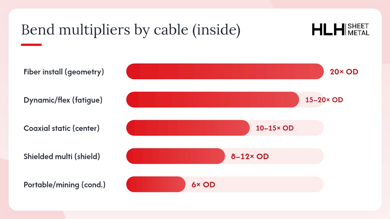
| Fiber optic — installation pull | 20× OD | Fiber geometry, attenuation | Inside radius | 20 in |
| Fiber optic — long-term installed | 10× OD | Fiber geometry, long-term attenuation | Inside radius | 10 in (254 mm) |
| Shielded multiconductor — static | 8–12× OD | Shield geometry, insulation | Inside radius | 8–12 in |
| Coaxial cable — static | 10–15× OD | Center conductor, dielectric | Inside radius | 10–15 in (254–381 mm) |
| Portable/mining cable — static | 6× OD (min) | Conductors, jacket | Inside radius | 6 in |
| Dynamic/flex (continuous motion) | 15–20× OD or per datasheet | Conductor fatigue life | Inside radius | 15–20 in |
| Sheet metal (soft copper, annealed) | 0T | Surface integrity | Inside radius | N/A — use thickness |
| Sheet metal (5052-H32 aluminum) | 1T | Surface integrity, grain | Inside radius | N/A — use thickness |
| Sheet metal (6061-T6 aluminum) | 3–4T | Surface integrity, grain | Inside radius | N/A — use thickness |
The FOA’s installation guidance is the primary source for the fiber multipliers. Anixter’s wire wisdom reference covers shielded power, coaxial, and multiconductor classes with worked examples. The ServiceWire reference tables map conductor diameter ranges to minimum bending multipliers for shop use.
NASA-STD-8739.4 supplies both an optimum design target and a minimum hard limit for aerospace harness assemblies. Design to the optimum when space and weight allow; treat the minimum as the acceptance floor, not the design target. For harnesses containing multiple cable types, the most restrictive cable governs the entire bundle’s bend radius unless a documented alternate rule is approved.
NEC (NFPA 70) and ICEA standards govern power cable installation in electrical construction. NEC Article 300 and the relevant ICEA product standards set minimum bending radii for specific conductor sizes and insulation types; these values are typically expressed as multiples of the cable OD or overall diameter and are enforced during conduit fill and routing inspections. Always check the applicable NEC table for the conductor size and insulation class you are working with.
DFM Checklist For Sheet Metal Bends
- Call out the inside radius explicitly on the drawing (e.g., “R3.0 mm INSIDE”).
- Specify the alloy and temper, not just the material family.
- Note grain direction when the bend is within 1T of the material minimum.
- Ask the fabricator for their minimum achievable radius before finalizing the design — tooling on hand often limits what is practically achievable.
- For radii tighter than 1T on aluminum or stainless, request a sample bend before committing to production.
- Include a minimum flange length callout. A flange shorter than the die opening width cannot be formed without special tooling; as a rule of thumb, minimum flange length is approximately 4× material thickness for standard tooling.
Pro Tip: For 6061-T6 parts with tight bend radii, ask your fabricator whether ordering the material in the -O (annealed) condition and bending before aging is feasible. It often cuts rework rates significantly on complex brackets.
Installation, Static, And Dynamic Bend Radii: Why The Difference Matters
These three service conditions require three different multipliers, and applying the wrong one is a common source of premature cable failure.
Installation (pull) radius applies while the cable is being routed — pulled through conduit, over sheaves, or around corners under tension. Mechanical stress is highest during this phase. The FOA recommends 20× OD as a safe installation radius for many fiber cables precisely because tensile load during pulling amplifies the bending stress at the outer surface. A practical trap: the minimum bend radius is a radius, not a diameter. When routing over a sheave or pulley, the pulley diameter must be at least twice the minimum bend radius. Confusing radius with diameter produces pulleys that are half the required size.
Long-term static (installed) radius applies once the cable is in place and not moving. Stress relaxes, and a smaller radius is acceptable. FOA’s 10× OD recommendation for installed fiber reflects this. The cable still must not be kinked or pinched, but the sustained mechanical load is far lower than during installation.
Dynamic (flex) radius applies when the cable moves repeatedly — in cable carriers, robotic arms, or any application with continuous flexing. Fatigue is the governing failure mode, not peak stress. Dynamic radii are typically 15–20× OD or more, and the datasheet for a flex-rated cable will specify a cycle count at a given radius. Never substitute a static-rated cable in a dynamic application without verifying the flex life data.
NASA-STD-8739.4’s distinction between optimum and minimum values maps onto this framework: the optimum target is appropriate for static aerospace harnesses where reliability margins must be high; the minimum is the acceptance floor for as-built inspections.
How To Measure And Inspect Bend Radius In The Field
Accurate measurement starts with the right tool for the geometry.
Tools and methods:
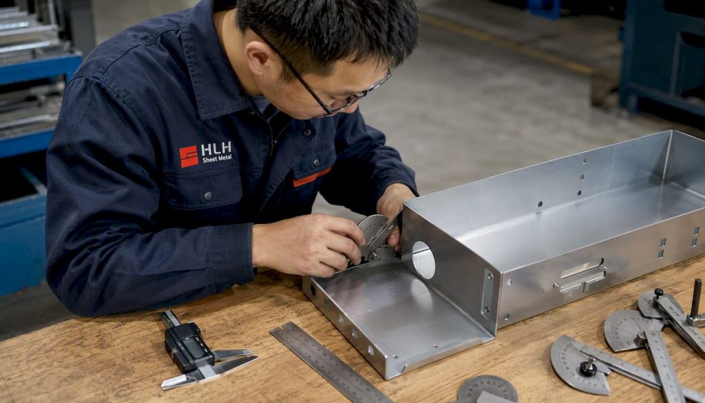
- Radius gauges (leaf-type): fast and practical for convex or concave surfaces on sheet metal and large-diameter cables. Match the gauge to the inside curve.
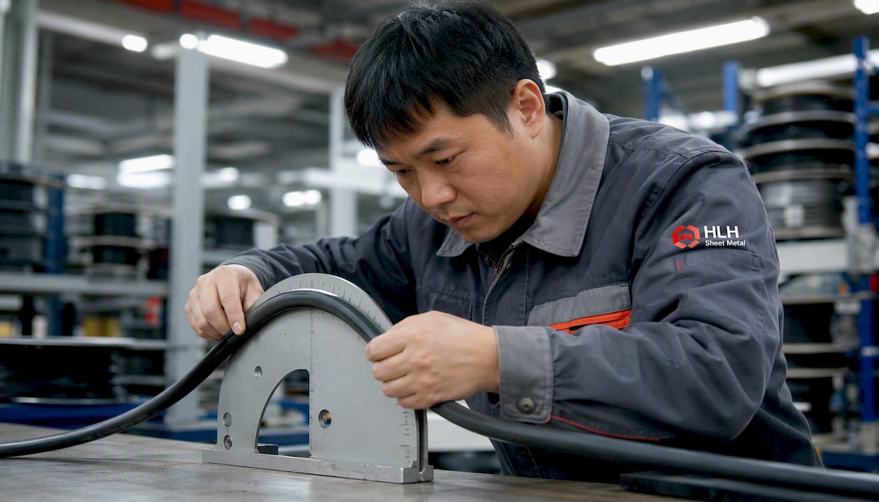
- Flexible radius templates: useful for cables in conduit where a rigid gauge cannot reach the inner arc.
- Calipers + arc-fitting: measure the chord length and sagitta (depth of arc), then calculate the radius geometrically. Useful when direct gauge access is blocked.
- Optical/photographic methods: photograph the bend against a calibrated scale, then fit a circle to the inner arc in CAD or image software. Practical for complex 3D harness routing.
Acceptance checklist:
- Record the cable or material OD (or thickness T) from the datasheet or a direct measurement.
- Record the governing multiplier and its source (datasheet, standard, or table).
- Compute the minimum acceptable radius and document it.
- Measure the actual inside radius at the tightest point of the installed bend.
- Confirm the measured radius is equal to or greater than the minimum.
- Note the measurement location (distance from connector, bulkhead entry, or conduit end).
- Sign and date the inspection record; attach the governing source reference.
When a bend fails inspection, the corrective options are: re-route to increase the radius, add a service loop, install a protective sleeve or bend limiter, or replace the cable with one rated for a tighter radius. Document the nonconformance and the corrective action taken before closing the record.
What Actually Fails When You Exceed The Minimum Bend Radius
Exceeding the minimum bend radius rarely causes instant failure. The damage accumulates, which makes it harder to catch and more expensive to fix.
For cables, the failure modes depend on construction. Conductors in a tight bend experience tensile stress on the outer side and compressive stress on the inner side; repeated cycling fractures individual strands, increasing resistance and eventually causing an open circuit. Insulation cracks at the outer surface, admitting moisture and creating leakage paths. Shielded cables lose shield coverage as the braid or foil distorts around a tight radius, degrading EMI performance. Fiber optic cables suffer increased attenuation first, then physical fiber fracture if the radius is severe enough.
For sheet metal, exceeding the minimum bend radius produces cracking on the outer surface (tensile failure of the material), thinning at the bend zone, and springback that is difficult to predict and correct. High-strength alloys like 6061-T6 are particularly unforgiving.
Pro Tip: The highest-risk locations in any cable run are connector backshells, bulkhead entries, and the first bend after a sheave or pulley. These are where the cable is most constrained and where installation stress concentrates. Add margin above the minimum at these points, not just at the tightest mid-run bend.
A typical installation mistake: a technician routes a shielded cable around a 90-degree corner in a panel, eyeballing the radius as “about right.” Six months later, intermittent EMI failures appear. The root cause is a bend radius below the shield’s minimum, which opened gaps in the braid. The corrective action is re-routing with a measured radius and adding a strain-relief clamp at the entry point.
Mitigations beyond re-routing include: switching to a more flexible cable construction, using a cable carrier or bend limiter rated for the required radius, selecting an annealed or lower-temper material for sheet metal, and adding service loops at every connector to absorb installation stress.
How To Specify Minimum Bend Radius On Drawings And In Procurement Documents
Vague callouts cause field failures. Specific, absolute callouts prevent them.
Preferred Drawing Callout Format
- State the minimum bend radius as an absolute dimension, not just a multiplier: “MIN BEND RADIUS = 45 mm (1.77 in) INSIDE”
- Add the measurement convention: “MEASURED TO INSIDE CURVE PER IPC/WHMA-A-620.”
- Note the service condition if both installation and static values apply: “INSTALLATION: MIN 90 mm; INSTALLED STATIC: MIN 45 mm.”
- For sheet metal, add the alloy and temper to the title block and call out the inside radius on the bend detail view.
- Reference the governing standard or datasheet by document number and revision.
Procurement Clause Fields For Rfqs
- Material, alloy, and temper (e.g., “5052-H32 aluminum, 0.090 in thick”).
- Required minimum bend radius — absolute value and multiplier (e.g., “MIN BEND RADIUS = 4.5 mm = 1T”).
- Service condition: installation, static, or dynamic/flex.
- Required inspection evidence: dimensional report, sample bend, or first-article inspection.
- Governing standard or datasheet document number.
- Finish requirements that may affect bend sequence (e.g., anodize after bending).
When manufacturer data and a governing standard conflict, use the more conservative (larger) radius and document the rationale in the design record. Never split the difference.
Three Worked Examples
Example 1: Fiber Optic Cable
A loose-tube fiber cable has a finished OD of 12 mm (0.47 in). The FOA recommends 20× OD for installation and 10× OD for the long-term installed condition.
- Installation radius: 20 × 12 mm = 240 mm (9.45 in)
- Installed static radius: 10 × 12 mm = 120 mm (4.72 in)
Route planning must accommodate 240 mm at every bend during the pull. Once installed and secured, 120 mm is the acceptance floor for inspection.
Example 2: Shielded Multiconductor Power Cable
A shielded, 600 V multiconductor cable has a finished OD of 1.25 in (31.75 mm). The Anixter reference table suggests 8× OD for static installation of this cable class.
- Minimum installed radius: 8 × 1.25 in = 10 in (254 mm)
If the installation involves pulling through conduit, apply a more conservative multiplier (15×) to account for tensile stress, per common practice and matched to FOA guidance for high-stress conditions. At 15×: 15 × 1.25 in = 18.75 in (476.25 mm). Use 18.75 in for routing design; verify 10 in at final inspection.
Example 3: Sheet Metal Bend
A 304 stainless steel bracket, 2 mm thick, requires a 90-degree bend. The minimum bend radius for 304 stainless at this thickness is 1T = 2 mm inside radius.
- Inside radius: 2 mm (0.079 in)
- Bend allowance (for flat-pattern): calculated using the K-factor for the tooling setup (typically 0.33–0.50 for press brake work). At K = 0.44 and a 90-degree bend: BA = (π/2) × (R + K × T) = 1.571 × (2 + 0.44 × 2) = 1.571 × 2.88 = 4.52 mm
Add this bend allowance to the flat-pattern length. Note on the drawing: “R2.0 INSIDE, 304 SS, 2 mm, GRAIN PERPENDICULAR TO BEND.”
These examples are illustrative. Always cross-check against the specific product datasheet and your fabricator’s confirmed tooling capabilities before releasing drawings.
Fabricator Checklist And DFM Tips
Getting bend radius right in production starts with what you put in the RFQ, not what you inspect at the end.
Fabricator checklist — what to include in your package:
- Material callout: alloy, temper, thickness, and material cert requirement (e.g., MTR for aerospace).
- Inside radius: absolute value in mm and inches, not just a multiplier.
- Grain direction: note “BEND LINE PERPENDICULAR TO ROLLING DIRECTION” when critical.
- Tooling note: specify punch nose radius if you have a hard requirement; otherwise let the fabricator select.
- Finish sequence: confirm whether anodize, powder coat, or plating happens before or after bending.
- Acceptance inspection: first-article inspection (FAI) with dimensional report, or sample bend with radius verification.
- Springback allowance: ask the fabricator to confirm their overbend angle for the material and thickness.
RFQ template fields for buyers:
- Material/temper and thickness (absolute, not nominal).
- Required minimum bend radius (absolute + multiplier, both).
- Service condition: static, installation, or dynamic.
- Required inspection evidence and acceptance criteria.
- Governing standard or datasheet document number and revision.
- Quantity: prototype run (1–5 pieces) vs. production quantity.
For prototyping, request a sample bend on scrap material before cutting production blanks. Include a flat-pattern proof in the package so the fabricator can verify bend allowance before forming. Allow at least one iteration cycle for springback correction on tight-radius bends in high-strength alloys.
HLH SHEET METAL’s custom sheet metal bending services cover the full range from prototype sample bends to high-volume production, with ISO-certified inspection at each stage. If you are working with a tight radius in 6061-T6 or 304 stainless and need a first-article bend report before committing to production, that is exactly the kind of request their team handles routinely.
Key Takeaways
The single most important rule: always use the most conservative bend radius value from the manufacturer datasheet, the governing standard, or a reference table, in that order of precedence.
| Point | Details |
|---|---|
| Measurement convention | Inspect and specify to the inside curve; document the convention on drawings to prevent acceptance disputes. |
| Multiplier precedence | Manufacturer datasheet overrides the governing standard, which overrides a generic table. |
| Fiber optic radii | Use 20× OD during installation pulls and 10× OD for the long-term installed condition per FOA guidance. |
| Sheet metal alloy matters | 5052-H32 bends to 1T; 6061-T6 requires 3–4T. Grain direction and tooling geometry both affect the achievable radius. |
| HLH SHEET METAL | Provides ISO-certified prototype and production bending with first-article inspection reports for validated bend radii. |
The Case For Designing To The Optimum, Not The Minimum
Most engineers treat the minimum bend radius as the design target. That is the wrong frame.
Standards like NASA-STD-8739.4 publish two values for a reason. The minimum is the acceptance floor: a part that hits exactly the minimum has zero margin. Any manufacturing variation, any measurement uncertainty, any material lot-to-lot difference in ductility pushes it below the limit. The optimum is where you should be designing, especially for anything that moves, flexes, or lives in a harsh environment.
The counterargument is real: tighter radii save space and weight, and in dense enclosures or aerospace harnesses, every millimeter counts. The right answer is not to ignore the constraint but to engage the fabricator early. A fabricator who knows the space envelope and the material can tell you whether the optimum radius is achievable with standard tooling or whether it requires a special punch nose. That conversation costs nothing at the design stage and can save significant rework cost later.
The other thing engineers underestimate is the installation phase. A cable routed to exactly its static minimum radius will almost certainly be bent tighter during installation, before it is secured. Building in a service loop at every connector and bulkhead entry is not over-engineering; it is the difference between a cable that lasts the design life and one that fails at the first maintenance cycle.
HLH SHEET METAL: Precision Bending With Verified Radii
When your design calls for a guaranteed inside radius on a production part, the gap between “the drawing says R3 mm” and “the part actually measures R3 mm” is where quality programs earn their keep. HLH SHEET METAL’s precision sheet metal fabrication service covers that gap with ISO-certified inspection, first-article bend reports, and a team that reads English-language drawings without a translation layer.
Submit your RFQ with material/temper, thickness, absolute inside radius callout, governing standard reference, and required inspection evidence. HLH SHEET METAL’s fabrication capabilities span laser cutting, press-brake bending, welding, and surface finishing across steel, aluminum, stainless, copper, brass, and specialty alloys. Multiple plants handle prototype quantities and full production runs with fast turnaround. Request a quote and include a sample-bend requirement in your package.
Useful Sources
The following standards and references are the primary sources for bend radius values and inspection requirements:
- FOA — Bend radius (installation vs installed guidance)
- NASA‑STD‑8739.4 — Workmanship standard for cable and harness assemblies
- Minimum Bend Radius | Anixter
- MINIMUM BENDING RADII FOR CABLES — ServiceWire (reference tables PDF)
- Sheet Metal Minimum Bend Radius Chart (Free PDF) | RivCut
- Sheet Metal Bend Radius & Bend Allowance Calculator | MechSimulator
- Bend Radius Calculator: Calculate Minimum Bend Radius, Bend Allowance & K-Factor
- Bend radius — Wikipedia (summary of conventions and fallbacks)
Manufacturer datasheets take precedence over all of these. When a product-specific datasheet exists, use it. When it does not, start with the applicable standard and treat generic tables as a conservative fallback only.
FAQ
What Is The NEC Code For Cable Bending Radius?
NEC (NFPA 70) Article 300 and the relevant product articles set minimum bending radii for conductors and cables; the specific multiplier depends on conductor size, insulation type, and cable construction, so consult the applicable NEC table and the ICEA product standard for your exact cable class.
What Is The Minimum Bend Radius For 12 AWG Wire?
For a single 12 AWG conductor, the NEC and most manufacturer datasheets specify a minimum bending radius of approximately 5× the cable OD for fixed wiring; the finished OD varies by insulation type, so confirm the OD from the product datasheet and apply the governing multiplier.
How Do You Calculate Minimum Bend Radius?
Multiply the reference dimension (finished OD for cables, material thickness T for sheet metal) by the governing multiplier from the manufacturer datasheet or applicable standard; for example, a cable with a 0.75 in OD and a 10× static multiplier has a minimum installed bend radius of 7.5 in (190.5 mm).
What Is The Minimum Bend Radius For Sheet Metal?
Minimum bend radius for sheet metal is expressed as a multiple of material thickness (T) and varies by alloy and temper: soft copper bends to 0T, 5052-H32 aluminum to 1T, and 6061-T6 aluminum typically requires 3–4T; always verify against the specific alloy chart and your fabricator’s tooling.
What Is The Minimum Bend Radius Operation?
The minimum bend radius operation is the forming step that bends a material to its tightest allowable radius without cracking, thinning, or degrading performance; in press-brake work, it requires matching the punch nose radius to the material minimum and selecting a V-die opening that avoids excessive thinning at the bend zone.
