



Table Of Contents
Get your CAD right before you send files to China, and you can cut part costs by a meaningful margin while avoiding the rework cycles that blow lead times. The core moves: set your K-factor correctly (start at 0.44 for mild steel, adjust per material), enforce minimum bend radii of 1T–2T relative to material thickness, keep holes at least 2.5T from bend tangent lines, export validated DXF flat patterns alongside your STEP files, and ship a complete file package the shop can act on without calling you.
Highest-impact CAD actions to take now:
- Set the correct K-factor and material-specific bend table before modeling any flanges
- Enforce inside bend radius at 1T minimum (1.5T–2T for harder alloys like 5052 aluminum)
- Keep all holes and slots at least 2.5T from the nearest bend tangent
- Validate your flat pattern in-software before export — never send an unverified unfold
- Export STEP or IGES for 3D geometry plus DXF for every flat pattern
- Include an annotated 2D drawing with critical tolerances called out explicitly
- Specify material grade, thickness, and finish in the title block, not just in an email
- Design features to fit standard Chinese sheet sizes (1220 × 2440 mm is the dominant stock size)
Pro Tip: *Design your parts to nest efficiently on 1220 × 2440 mm sheets.
HLH SHEET METAL’s ISO-certified plants in China handle both prototypes and production runs, and their English-speaking engineering team can flag DFM issues before a single cut is made.
Key Takeaways
Correct CAD settings, validated flat patterns, and a complete file package are the three levers that most directly reduce cost and lead time on China sheet metal production runs.
| Point | Details |
|---|---|
| Set K-factor per material | Start at 0.44 for mild steel; build material-specific bend tables into your CAD template before modeling. |
| Validate flat patterns before export | Unfold and measure in-software every time — unverified DXF files are the most common cause of first-article failures. |
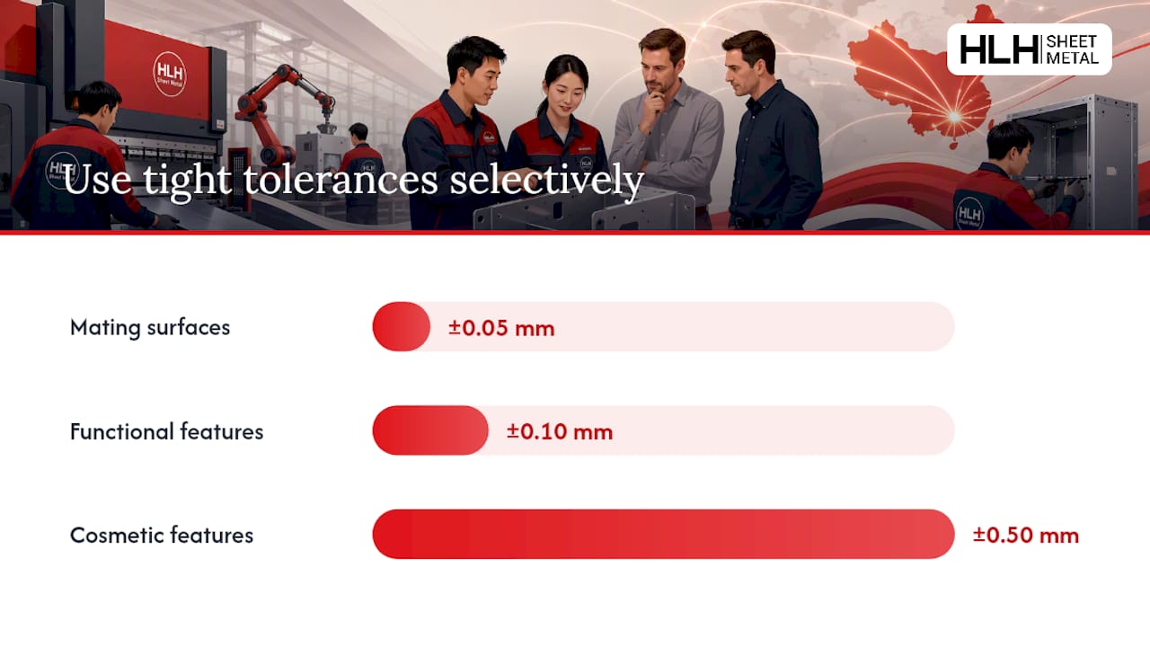
| Apply tight tolerances selectively | Use ±0.05 mm only at mating surfaces; ±0.1 mm for functional features; ±0.5 mm for cosmetic ones. |
| Design for standard Chinese sheet sizes | 1220 × 2440 mm is dominant stock; parts that nest at 75%+ yield, cost less per unit than complex profiles. |
| HLH SHEET METAL for DFM support | ISO-certified China fabrication with English-speaking DFM review, prototyping, and production — request a quote before tooling. |
Why Does DFM For China Cost More When You Get It Wrong?
Manufacturing in China offers real price advantages, but those advantages evaporate fast when your design forces non-standard tooling, excessive setups, or late-stage rework. Industry analysis reports up to ~40% higher production costs from manual rework, tool wear, and scrap when parts are not optimized for fabrication. That figure is not a rounding error — it is the difference between a profitable run and one that wipes your margin.
The cost structure in China differs from North American or European shops in a few specific ways:
- Tooling amortization is front-loaded. Custom punches, special dies, and non-standard forming tools are quoted as one-time charges. A design requiring three custom punches adds fixed cost that only dilutes at high volumes.
- MOQ pricing tiers are real. Chinese shops often price in bands (50, 200, 500, 1000 units). A design that forces a second setup — say, a part that can’t be nested with its siblings — can push you into a higher-cost tier.
- Laser vs. turret economics differ. Fiber laser cutting dominates in Chinese shops for complex profiles and small runs. Turret punching is cheaper per hit at high volume but requires standard punch geometry. Designing for the wrong process adds cost.
- Landed cost amplifies every defect. A scrap rate that costs $0.50 per part in a local shop costs $0.50 plus freight, import duty, and three weeks of delay when the parts are coming from Shenzhen.
For a direct cost comparison between China and other regions, the gap is significant — but only when the design is production-ready before it crosses the ocean.
Stat to know: Minor design oversights can raise production costs by as much as 40% through rework, tool wear, and scrap — making early DFM review one of the highest-ROI steps in any China production program.
DFM best practices consistently point to the same conclusion: integrate DFM early, apply tight tolerances only where function demands them, and budget prototype iterations before cutting production tooling.
Which CAD Settings Actually Matter For Sheet Metal DFM?
The four settings that cause the most downstream problems are K-factor, bend radius, flat-pattern validation, and export format. Get these right in your CAD template and the rest of the workflow follows.
K-factor And Bend Tables
Autodesk Fusion’s sheet metal tools expose a default K-factor of 0.44, which is a reasonable starting point for mild steel (CRS) at standard thicknesses. Harder materials shift it: 304 stainless typically runs 0.44–0.50, 5052 aluminum closer to 0.40–0.45. The right approach is to build material-specific bend tables into your CAD template rather than relying on a single global value. Every time you switch material or thickness, the bend allowance changes — and a flat pattern generated with the wrong K-factor will produce parts that don’t close correctly.
Onshape’s sheet metal environment keeps folded and flat views in sync automatically, so any change to a bend parameter updates the flat pattern in real time. That live sync is what you want: it eliminates the manual re-export step that causes version drift between your 3D model and the DXF you send to the shop.
Designcenter Solid Edge generates NC-ready flat patterns using industry-standard formulas and includes automatic bend table creation, which reduces the chance of a shop applying their own assumptions to your geometry. SolidWorks, through its 3D SheetMetal Creator environment, adds automated nesting and turret recognition — useful when you’re coordinating with a shop running CNC turret presses.
File Formats And Deliverables
Send three things minimum:
- STEP or IGES for the 3D solid (parametric, not mesh — factories cannot reliably manufacture precision parts from STL files)
- DXF flat pattern for every sheet metal part, validated in-software before export
- Annotated 2D drawing with critical tolerances, bend notes, and finish callouts
DXF scale must be 1:1. Confirm units (mm, not inches) before export — unit errors are one of the most common causes of first-article failures in Chinese shops.
Pro Tip: Build a CAD template with your company’s standard bend table, preferred material thicknesses (1.0, 1.5, 2.0, 3.0 mm are the most stocked in China), and a title block that includes material grade, finish, and revision number. Every new part starts from that template — it takes 20 minutes to set up and saves hours of back-and-forth per project.
What Are The Process Limits For Laser Cutting, Bending, And Stamping?
Each process has hard geometric limits. Designing past them doesn’t just raise cost — it can make a feature unbuildable on standard equipment.
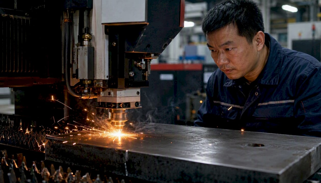
Laser cutting handles complex profiles and small features well, but minimum hole size still applies — a hole smaller than the material thickness risks taper and poor edge quality. Kerf width on a fiber laser runs roughly 0.1–0.2 mm for steel under 3 mm; account for this in tight-tolerance slot fits.
Turret punching is cost-effective for high-volume rectangular cutouts and standard hole patterns, but special punch shapes (non-round, non-square) trigger tooling charges. Slug retention — where a punched slug doesn’t fall clear — is a real production problem; design slots with a width-to-length ratio no greater than 1:5 to minimize it.
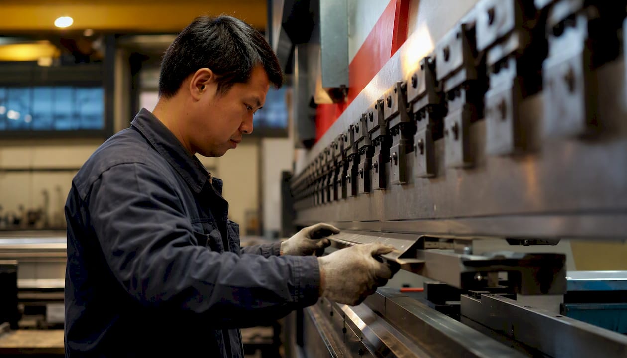
Press brake bending requires adequate flange length for the tooling to grip. A flange shorter than 4T can’t be formed reliably on standard tooling. Bend sequence matters too: plan the order of bends so earlier bends don’t block the tooling path for later ones. For complex parts, sketch the bend sequence in your drawing notes.
Welding and assembly: design weld access into the geometry. A joint that requires a torch at a 15-degree angle in a 30 mm channel will be skipped or done poorly. Standard jig fixturing in Chinese shops assumes flat datum surfaces — design one flat reference face per assembly wherever possible.
Finishes: powder coat and wet paint add 0.05–0.15 mm per surface. Holes used for fastener clearance need to account for that buildup. Anodizing on aluminum adds 0.01–0.025 mm per surface and can affect tight bore fits. Call out pre-finish vs. post-finish dimensions explicitly.
How Do China-specific Constraints Change Your CAD Decisions?
The economics of Chinese fabrication reward a specific set of design behaviors. Understanding them lets you make CAD choices that directly lower your quote.
- Nesting efficiency is priced in. Shops run DXF files through nesting software before quoting. A part with a complex profile that wastes 40% of a blank will cost more per unit than a simpler profile that tiles at 80%+ yield. Where function allows, add small flats or simplify curves to improve nesting.
- Standard material thicknesses stock cheaply. In China, 1.0, 1.2, 1.5, 2.0, 2.5, and 3.0 mm cold-rolled steel and 1.0, 1.5, 2.0, and 3.0 mm 5052 aluminum are the most readily available. Specifying 1.8 mm or 2.2 mm forces a special order and adds lead time.
- Alloy substitution is common. Chinese shops may substitute Q235 for A36, or 6061-T6 for 6063-T5, without flagging it unless you specify. Call out the exact alloy designation and, for structural or corrosion-critical parts, require a material certificate (MTR).
- Clear file packages shorten review cycles. Chinese fabrication shops value standardized handoff packages: STEP + DXF + bend table + a single-page manufacturing summary. That clarity reduces the back-and-forth that adds days to your lead time. Version your files clearly (PartName_Rev_A_FlatPattern.dxf) and include a simple change log.
- Standard tooling vs. custom tooling: accept factory standard tooling for non-critical features. Reserve custom tooling requests for features where function genuinely requires it — and when you do specify custom tooling, confirm the shop can amortize it across your expected volume.
Pro Tip: Consolidate part families. If you have six bracket variants that differ only in hole pattern, design a common blank and use secondary operations to differentiate them. One blank = one nesting program = one material order. The per-part cost drops noticeably at volumes above 200 units.
For a deeper look at pricing factors in China, setup charges, material surcharges, and finish costs all interact with your CAD choices in ways that aren’t always obvious from a quote sheet alone.
What Goes In A Manufacturing-ready File Package For A Chinese Shop?
A complete handoff eliminates the most common source of delay: the shop emailing back to ask what you meant. Structure your package like this:
File checklist (ordered by priority):
PartName_Rev_A.STEP— 3D solid, millimeters, no meshPartName_Rev_A_FlatPattern.DXF— 1:1 scale, mm, validated unfoldPartName_Rev_A_Drawing.PDF— annotated 2D with critical tolerances, bend notes, finish calloutsBendTable_MaterialGrade_Thickness.xlsx— K-factor, bend allowance, bend deduction per radiusFinishSpec.PDF— color, coating type, thickness, masking requirementsMaterialAlternatives.TXT— acceptable substitutions with conditions (e.g., “Q235 acceptable if MTR provided”)AssemblyNotes.PDF— weld locations, fastener specs, datum references
Manufacturing summary (one page, answers the shop’s top questions):
- Critical dimensions and tolerances (call out ±0.1 mm vs. ±0.5 mm zones explicitly)
- Material grade and finish
- Production quantity and MOQ
- Inspection criteria (first-article inspection required? CMM? Visual only?)
- Contact name and response time expectation
ZIP structure: /Rev_A/3D/, /Rev_A/2D/, /Rev_A/BendTables/, /Rev_A/Specs/, plus a README.txt with your name, email, phone, and a one-line description of the part. Export settings: confirm mm units, 1:1 scale, and ASCII DXF format (not binary) for broadest compatibility with Chinese CAM software.
What CAD Mistakes Cause The Most Expensive Problems In China?
Most cost overruns trace back to a short list of repeatable errors. Here’s what to check before you send anything.
- Wrong K-factor: flat pattern is wrong, parts don’t close. Fix: set material-specific K-factor in your CAD template before modeling. For mild steel, start at 0.44 and confirm with your shop’s bend test data.
- Holes too close to bends: material deforms around the hole during bending, turning a round hole into an oval. Fix: move all holes and slots to at least 2.5T from the bend tangent line — 3T if the hole is load-bearing.
- Over-tight tolerances everywhere: a drawing that calls ±0.05 mm on every feature triggers inspection costs and rejection rates. Fix: apply tight tolerances only to mating or functional surfaces; use ±0.1 mm for non-critical features and ±0.5 mm for cosmetic ones. Tight tolerances only where function demands them is a core DFM principle.
- No flat pattern supplied: the shop unfolds your part using their own assumptions, which may not match your K-factor. Fix: always export and validate the flat pattern in your CAD tool before sending.
- Wrong file format: STL or mesh files sent instead of STEP. Fix: STEP for 3D, DXF for flat patterns — every time.
- Ignoring nesting: complex profiles that waste blank material. Fix: simplify outer profiles where function allows; add small tabs or flats to improve tile efficiency.
When in doubt about a new feature or tight tolerance, run a prototype before committing to tooling. A small prototype batch — even 5–10 parts — validates your flat pattern, bend sequence, and finish spec before you’re locked into a production run. AI-assisted DFM tools can also flag common geometric violations automatically before you send files.
How Much Can CAD Changes Actually Save On A China Production Run?
The answer depends on the starting point, but the pattern is consistent: standardizing material thickness, correcting bend radii, and consolidating blanks produce measurable cost reductions on most production programs.
Before/after summary:
- Material thickness variants: 4 → 2 (eliminates two material orders and two nesting programs)
- Nesting yield: ~30% → ~75% (direct reduction in material cost per part)
- Tolerance zones: global ±0.05 mm → functional ±0.05 mm / non-critical ±0.1 mm (reduces inspection time and rejection rate)
- Bend radius: non-standard 0.5 mm → standard 1.5 mm (eliminates custom tooling charge)
The result: Design oversights that go uncorrected can raise production costs by up to 40% — which means correcting them before production is where the real savings live.
The lead-time impact is often as significant as the cost impact. Fewer setups, standard materials, and a clean file package can shorten a China production cycle by days — sometimes more than a week on complex assemblies.
The CAD Mistake Most Engineers Underestimate
The single most common oversight is not the K-factor — it’s the flat pattern. Engineers spend hours perfecting the 3D model and then export an unvalidated DXF as an afterthought. The shop receives it, unfolds it with their own parameters, and the first-article parts come back with flanges 1–2 mm short. Everyone assumes the press brake operator made an error. The real cause was a flat pattern that was never checked.
The fix takes five minutes: unfold the part in your CAD tool, measure the flat against your expected blank size, and confirm the bend allowance matches your bend table. If it doesn’t, the K-factor is wrong — fix it in the template, not just for this part.
On the question of which features deserve tight tolerances: mounting holes and mating flanges, yes. Cosmetic cutouts, cable routing slots, and ventilation patterns, no. Applying ±0.05 mm to a ventilation slot adds inspection cost and zero functional value. Save the precision budget for the three or four dimensions that actually determine whether the assembly works.
The other thing most guides don’t say clearly: Chinese shops are good at following a clear spec and bad at guessing what you meant. A drawing with ambiguous callouts doesn’t get a phone call — it gets interpreted. The interpretation is usually wrong. Write the manufacturing summary as if the reader has never seen your product before, because the person quoting it probably hasn’t.
HLH SHEET METAL Cuts Your DFM Review Time And Production Cost
Applying every rule in this guide takes engineering time — time most product teams don’t have before a launch deadline. HLH SHEET METAL offers CAD DFM reviews, prototype runs, and ISO-certified sheet metal fabrication in China with English-speaking engineers who catch the flat-pattern errors, tolerance mismatches, and nesting inefficiencies before they become production problems.
Practical services available:
- DFM review and CAD cleanup before quoting
- Prototype runs (low MOQ, fast turnaround)
- Nesting optimization and material yield analysis
- Tooling management for custom features
- First-article inspection and QC reporting
HLH SHEET METAL’s multi-plant China operations handle everything from single prototypes to high-volume production runs across steel, aluminum, stainless, and specialty alloys. Get a quote or request a DFM review at HLH Sheet Metal.
Sources
- Onshape sheet metal
- Autodesk Fusion sheet metal software
- Sheet metal fabrication in China: 5 advanced DFM strategies to optimize manufacturing costs — WriteUpCafe
- Design for Manufacturing Guide: DFM best practices | OPD Design
FAQ
What Are The DFM Guidelines For Sheet Metal?
Core DFM guidelines for sheet metal include maintaining a minimum inside bend radius of 1T (1.5T–2T for harder alloys), keeping holes at least 2.5T from bend tangent lines, applying tight tolerances only to functional surfaces, and always supplying a validated DXF flat pattern alongside your STEP file.
What Is The Best CAD Software For Sheet Metal Fabrication?
Onshape, Autodesk Fusion, SolidWorks, and Designcenter Solid Edge all include native sheet metal environments with bend tables, K-factor controls, and flat-pattern export. The best choice depends on your workflow: Onshape for cloud-based live sync, Fusion for integrated CAD/CAM, Solid Edge for NC-ready flat patterns.
What Is A DFM Checklist For Sheet Metal?
A sheet metal DFM checklist covers: correct K-factor and bend table set in CAD, minimum bend radii enforced, holes and slots clear of bend tangents, validated flat pattern exported as DXF, STEP file for 3D geometry, annotated 2D drawing with tolerances, and a one-page manufacturing summary with material, finish, and inspection criteria.
Which Software Is Best For Sheet Metal Design In China Manufacturing?
Any CAD tool with a native sheet metal environment works, but the file output matters more than the tool itself. Chinese shops need STEP or IGES for 3D and DXF flat patterns at 1:1 scale in millimeters. Autodesk Fusion and Onshape both export these formats directly and support the K-factor and bend table settings Chinese fabricators expect.
How Do You Reduce Sheet Metal Part Cost When Manufacturing In China?
Design for standard material thicknesses (1.0, 1.5, 2.0, 3.0 mm), simplify profiles to improve nesting yield on 1220 × 2440 mm stock sheets, consolidate part families to share blanks, and apply tight tolerances only where function requires them.
