




For production runs, the most reliable approach to countersink sheet metal is to use formed or punched countersinks applied at the blank stage, before bending. Reserve drilled or CNC-machined countersinks for prototypes, low-volume runs, or joints that require precise seat geometry. For gauges below 0.8 mm, skip direct countersinking entirely and specify PEM self-clinching inserts or rivet nuts instead.
Three anchors for any production decision:
- Process match: Formed countersinks at the blank stage give the best repeatability at mid-to-high volumes. Machined secondary ops give the tightest seat geometry at low volumes.
- Quality standard: Require ISO 9001 certification from any fabricator producing countersunk parts for structural or cosmetic applications.
- Thin-gauge rule: Sheet thinner than roughly 0.8 mm cannot hold a reliable countersunk fastener. PEM self-clinching inserts, rivet nuts, or blind rivets are the production-proven alternatives.
HLH SHEET METAL handles all of these methods across multiple facilities, from single prototypes to high-volume production runs, with ISO-certified QA at every stage.
Table Of Contents
What Production Methods Create Countersinks In Sheet Metal?
Four methods cover nearly every production scenario. The right one depends on your volume, required tolerance, and part geometry.
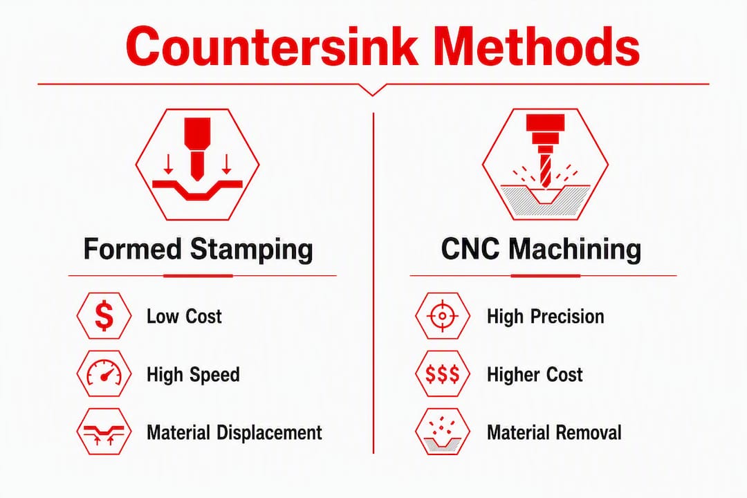
Formed (stamped) Countersinks
A punch-and-die set displaces material downward to create the countersink profile without removing metal. This is the fastest method at volume and produces a work-hardened seat that resists pull-through. Tooling cost is higher upfront, but per-part cost drops sharply once amortized. Formed countersinks work best in aluminum and mild steel at moderate gauges suitable for typical fabrication ranges. Stainless steel can be formed but requires more robust tooling and tighter springback compensation.
CNC Punching With Countersink Tooling
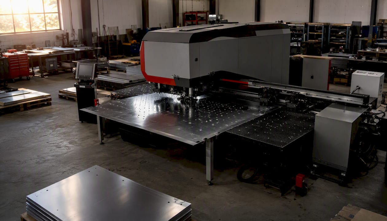
Turret punch presses fitted with countersink tooling can produce consistent seats in a single hit, integrating the feature into the flat-blank program. This method suits mid-volume runs where the part already goes through a punch press for other features. Tolerances are tighter than hand-formed but slightly looser than machined. Setup time is low once the tool is in the turret.
CNC Drilling And Machining (secondary Ops)
After laser cutting or punching, a CNC machining center drills the pilot hole and runs a countersink bit to the specified seat diameter and angle. This is the most precise method, capable of holding seat diameter to ±0.05 mm and angle to ±0.5°. It is also the most expensive per part at volume because it requires a separate machine setup. For prototypes and runs under roughly 50 pieces, the absence of tooling cost makes it the practical default.
Manual Countersinking For Prototypes
A handheld or drill-press-mounted countersink bit produces acceptable results for one-off parts and fit checks. Consistency depends entirely on operator skill and feed control. Never specify this method for production.
Comparison by method:
| Method | Best for | Thickness range | Materials | Achievable tolerance | Relative cost per part | Typical lead time |
|---|---|---|---|---|---|---|
| Formed/stamped | suit mid to high production volumes | typical sheet gauges | providing good tolerances | lower per-part costs | fast, suitable for volume production | |
| CNC punch with countersink | low to mid production volumes | common sheet metal gauges | balancing tolerance | cost effectively | moderate lead times | |
| CNC secondary machining | prototypes and low volumes | suitable for a range of metals including stainless and titanium | offering the highest precision | higher per-part cost | longer lead times | |
| Manual (drill press) | Prototype/fit check only (1–5) | 0.8 mm+ | Aluminum, mild steel | ±0.15 mm | Very low | Same day |
When a part is laser-cut and requires a countersink, the laser operation produces the pilot hole location, and a secondary CNC step creates the seat. Flag this as a “secondary op” in your RFQ so the fabricator quotes it separately and schedules the correct machine time. Combining the laser and secondary op in a single quote request avoids the most common scheduling gap that extends lead times.
Key process selection rules:
- Formed countersinks require a minimum material thickness sufficient to avoid tearing at the seat edge during forming.
- CNC punching requires the countersink to be at least 3× the material thickness away from any bend line.
- Machined secondary ops are the only reliable method for 100° seats in stainless steel above 1.5 mm.
What Design Rules And Callouts Do Engineers Need For Countersinks?
Seat Angle Selection
Standard countersink angles are 82°, 90°, and 100°. The 82° angle matches unified inch-series flat-head screws (the most common in North American production). The 90° angle matches metric flat-head screws per ISO standards. The 100° angle is used for aerospace and some military fasteners. Mismatching the seat angle to the fastener is the single most common drawing error on countersunk parts: a 90° screw in an 82° seat will rock; an 82° screw in a 90° seat will bottom out on the shank before the head seats flush.
Countersink charts from fabricators provide seat diameters and clearances for standard screw sizes, useful for confirming design requirements. Use it to confirm your seat diameter before releasing drawings.
Depth And Thickness Rules
A practical design guideline is that countersink depth should not exceed approximately half the material thickness to maintain structural integrity. Below that threshold, the remaining wall section becomes too thin to carry load reliably. The minimum sheet thickness for a direct countersink is generally about twice the countersink depth; for common screw sizes, this implies a material thickness that supports the specified seat depth and diameter.
Recommended Tolerances
| Feature | Recommended tolerance |
|---|---|
| Hole location | ±0.1 mm |
| Seat diameter | ±0.1 mm |
| Countersink depth | ±0.05 mm |
| Seat angle | ±1° |
Drawing Callout Format
A complete countersink callout on a flat-pattern drawing reads:
∅4.2 THRU / ∅9.4 × 82° CSK
That string specifies: pilot hole diameter, through-hole, seat diameter, and seat angle. Add a secondary-op flag (e.g., “SEC OP: CSK”) when the feature is machined after laser cutting, so the fabricator’s router assigns it to the correct work center.
Pro Tip: Never tolerance a formed countersink to the same ±0.05 mm depth tolerance you would apply to a machined seat. Formed features move with springback and material variation. Use ±0.15 mm for formed seats and reserve tight tolerances for machined ops only.
Additional callout items to include:
- Flat pattern note: “All countersinks applied pre-bend unless noted.”
- Screw head flush requirement: “CSK seat to flush with #10-32 flat-head per ASME B18.6.3.”
- Secondary op flag on the title block: “Secondary operations: see op sheet.”
How Does Material Type Affect Countersink Feasibility?
Aluminum
Aluminum alloys (6061-T6, 5052-H32) form countersinks cleanly at gauges from 1.0 mm to 4.0 mm. Springback is moderate and predictable. Punched or formed countersinks work well at mid-to-high volume. Watch for galling on the seat surface when using HSS tooling at high speeds; carbide-tipped countersink bits reduce this. Anodized aluminum can show cosmetic witness marks around formed seats, so specify post-form anodizing when cosmetics matter.
Stainless Steel
Grades 304 and 316 work-harden rapidly during forming, which means a formed countersink that looks acceptable in mild steel may crack at the seat edge in 17-4 PH or 316L at thin gauges. For stainless above 1.5 mm, machined countersinks with carbide tooling are the reliable choice. Thin stainless (under 1.2 mm) is better served by self-clinching inserts. Common countersinking mistakes in stainless include excessive cutting speed and dull edges, both of which cause seat tearing and burrs that prevent flush seating.
Galvanized And Pre-painted Steel
Forming a countersink in galvanized or pre-painted material cracks the coating at the seat edge. Two options: machine the countersink after forming (which removes coating locally and requires touch-up), or form before coating and specify the countersink as a pre-coat feature. The second option is almost always cleaner for production. Flag coating sequence explicitly in your process notes.
Very Thin Gauges (below 0.8 Mm)
Direct countersinking in sheet thinner than 0.8 mm produces a seat with almost no bearing area. Thin sheet often cannot hold threaded fasteners reliably; self-clinching hardware, rivet nuts, or blind rivets provide more durable joints in these gauges. The countersink geometry simply does not leave enough material to resist pull-through under load.
When Is Direct Countersinking Too Thin, And What Are The Alternatives?
The practical minimum for a direct countersink is 1.0 mm for formed features and 0.8 mm for machined seats. Below those thresholds, the joint will not meet typical pull-out requirements for production assemblies.
Alternatives by use case:
- PEM self-clinching nuts and standoffs: Pressed into the flat blank before bending, these give full-strength threads in gauges as thin as 0.5 mm. They are the default choice for PCB mounting structures and panel fastening in electronics enclosures. Designers should apply inserts while the blank is flat so tooling seats fully; installing them after bending often prevents complete seating.
- Rivet nuts (sert nuts): Installed from one side after forming, rivet nuts work where access to both faces is limited. They suit field-installed hardware and repair scenarios better than production-line assembly.
- Blind rivets: For permanent, non-serviceable joints in thin sheet, blind rivets outperform threaded fasteners in vibration resistance and shear loads. No countersink required; the rivet head sits proud or flush depending on the head style specified.
- Clinch studs: Pressed in at the blank stage, clinch studs provide a permanent threaded post without any countersink. Useful for panel-to-panel assemblies where a nut is not accessible.
Pro Tip: Install PEM inserts and clinch studs on the flat blank, before any bending operation. Attempting to press them in after bending restricts tooling access and frequently results in incomplete seating, which causes assembly failures downstream.
How Do You Choose The Right Countersinking Process By Volume And Cost?
Volume is the primary driver. Tooling cost is the secondary one. Here is how the math works in practice.
Volume breakpoints:
- Prototype (1–20 pieces): CNC secondary machining or manual drill-press countersinking. No tooling investment. Per-part cost is high but total cost is low. Lead time: 3–7 days.
- Low volume (20–500 pieces): CNC punching with countersink tooling or machined secondary ops. Tooling cost for a punch-press countersink tool runs in the range of a few hundred dollars and amortizes quickly. Per-part cost drops noticeably versus manual methods.
- Mid volume (500–5,000 pieces): Formed/stamped countersinks become cost-competitive. Tooling investment is higher, but per-part cost at this range makes it the right call for most aluminum and mild steel parts.
- High volume (5,000+ pieces): Formed countersinks at the blank stage, integrated into the stamping program. Per-part cost is lowest; tooling cost is fully amortized within the first production run.
| Volume range | Recommended method | Tooling cost | Per-part cost | Lead time |
|---|---|---|---|---|
| 1–20 | CNC secondary machining | None | High | 3–7 days |
| 20–500 | CNC punch + countersink tooling | Low | Medium | 3–7 days |
| 500–5,000 | Formed/stamped | Medium | Low | 1–3 days at volume |
| 5,000+ | Formed/stamped (integrated) | Medium-high | Very low | — |
When writing an RFQ, ask for per-part cost with and without tooling, tooling ownership terms, and minimum order quantities for each process option. That gives you an apples-to-apples comparison across fabricators and lets you calculate the break-even volume where forming beats machining.
One often-missed detail: ask whether tooling is stored on-site for repeat orders. A fabricator who retains your countersink punch tooling cuts setup time and cost on reorders significantly.
What QC Checks Catch Countersinking Failures Before Assembly?
Most countersink failures in production trace back to five root causes: wrong seat angle, seat diameter out of spec, excessive depth, burrs at the seat edge, and inconsistent seat flatness. Catching these before parts reach assembly saves rework costs that multiply quickly at volume.
Common mistakes to watch for:
- Specifying an 82° seat for a metric flat-head screw (which needs 90°), or vice versa.
- Countersink depth exceeding 50% of material thickness, leaving insufficient wall section.
- Distortion or dishing around the countersink from excessive forming force or thin material.
- Burrs at the seat edge from dull tooling or excessive cutting speed, preventing flush seating.
- Seat flatness variation from worn punch tooling or inconsistent feed on manual ops.
Inspection checklist:
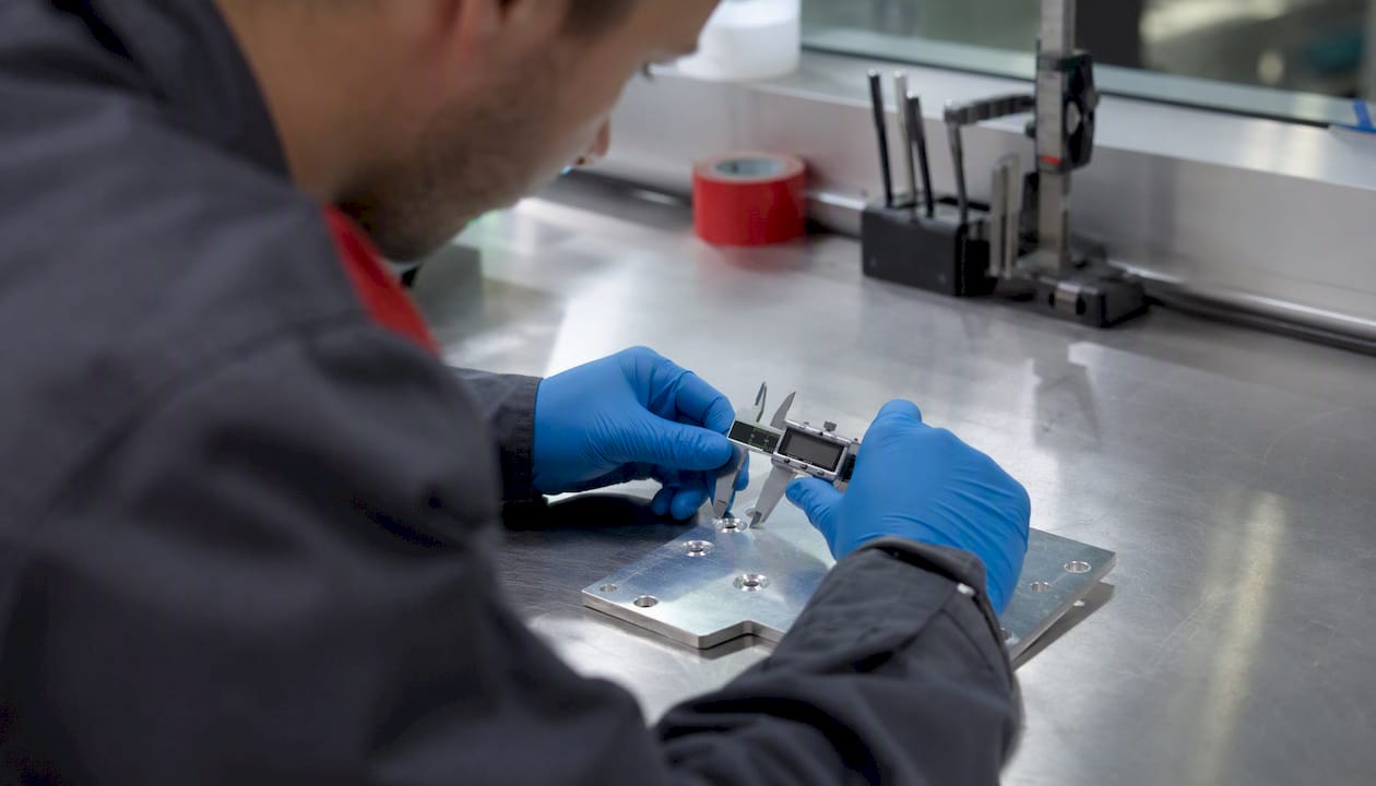
- Verify seat diameter with a calibrated optical comparator or CMM against drawing tolerance.
- Measure depth with a depth micrometer; confirm it does not exceed 50% of measured sheet thickness.
- Check seat angle with an angle gauge or CMM stylus sweep.
- Measure hole location runout relative to datum features on the flat pattern.
- Test-fit a representative production fastener: the head must sit flush or below flush with no rocking.
- Inspect seat surface for burrs under 10× magnification; any raised material at the seat edge is a reject.
Document acceptance criteria on the inspection report with the drawing revision number, lot number, and inspector sign-off. For incoming part inspections, request a first-article inspection (FAI) report from the fabricator that covers all six items above for the first production lot.
Pro Tip: Keep a go/no-go seat-fit gauge for each screw size you use regularly. A representative fastener torqued to spec in a sample countersink is the fastest and most reliable acceptance test on the shop floor.
What Do Fabricators Need On Drawings And In Rfqs To Produce Countersunk Parts Correctly?
Ambiguous drawings are the leading cause of countersink rework. A complete drawing package eliminates the back-and-forth that adds days to lead time.
Drawing requirements:
- Flat pattern with all countersink callouts in the format
∅[pilot] THRU / ∅[seat] × [angle]° CSK. - Hole schedule listing: hole ID, nominal diameter, location coordinates, positional tolerance, countersink seat diameter, angle, and depth or “seat to flush” note.
- Tolerance block covering hole location, seat diameter, depth, and angle separately.
- Secondary operation flag on the title block when countersinks are machined after laser cutting or forming.
- Material and finish callout, including coating sequence (pre- or post-countersink).
RFQ requirements:
- Request process options: formed vs. machined, with separate pricing.
- Ask for per-part cost with tooling included and tooling cost as a line item.
- Specify tooling ownership: does the tooling remain with the fabricator for reorders, and at what cost?
- Require a first-article inspection report covering seat diameter, depth, angle, location, and fastener fit.
- Request a sample seat-fit approval: one production part with a representative fastener installed, submitted before full-run release.
- Confirm surface-finishing compatibility: will the countersink be coated, anodized, or painted, and in what sequence?
Example callout to copy into your drawing notes:
∅4.2 THRU / ∅9.4 × 82° CSK — SEC OP, SEAT TO FLUSH WITH #10-32 FLAT-HEAD PER ASME B18.6.3 — TOL: SEAT DIA ±0.1, DEPTH ±0.05, ANGLE ±1°
Include a sample part with the first production shipment for seat-fit verification before full-run acceptance.
Send a reference part or a clear photograph of the cosmetic-facing surface when seat finish and deburr quality matter. Written callouts alone do not communicate the expected surface condition as clearly as a physical sample.
How Does HLH SHEET METAL Produce Countersunk Sheet-metal Parts?
HLH SHEET METAL’s fabrication capabilities cover the full range of countersink production methods: precision laser cutting for pilot hole location, CNC punch press with countersink tooling for mid-volume runs, CNC secondary machining for tight-tolerance seats, and stamping and forming for high-volume production. Multiple manufacturing facilities mean capacity scales from a single prototype to tens of thousands of parts without changing suppliers or re-qualifying a new vendor.
Industries served include aerospace, medical devices, automotive, HVAC, and robotics, all of which carry specific countersink tolerancing and surface-finish requirements. ISO certification backs every production run, and the team provides FAI reports, sample seat-fit approvals, and incoming inspection documentation on request.
What to ask for when you contact HLH SHEET METAL for countersunk parts:
Submit your flat pattern with countersink callouts, hole schedule, preferred process (formed or machined), material and finish spec, and required volume. Request a first-article inspection report and a sample seat-fit part before full-run release. The English-speaking engineering team reviews drawings and responds with a detailed quote, typically within one business day.
Key Takeaways
Formed countersinks at the blank stage give the best cost and repeatability for production runs above 500 pieces; machined secondary ops are the right call for prototypes and tight-tolerance seats.
| Point | Details |
|---|---|
| Match process to volume | Use CNC machining for 1–50 pieces; formed/stamped countersinks for 500+ pieces. |
| Respect minimum thickness | Direct countersinks require at least 1.0 mm (formed) or 0.8 mm (machined); use inserts below those limits. |
| Specify angle precisely | Call out 82° for unified inch-series screws, 90° for metric; a mismatch prevents flush seating. |
| Install inserts pre-bend | PEM self-clinching inserts and clinch studs must be pressed into the flat blank before any bending operation. |
| Use HLH SHEET METAL for production | HLH SHEET METAL handles laser cutting, punching, CNC secondary ops, and forming with ISO-certified QA and FAI reporting. |
The Detail Most Engineers Overlook On Countersunk Parts
The angle mismatch problem gets discussed constantly, and rightly so. But the issue that actually causes the most rework in production is sequencing: specifically, when inserts and formed features get added to the part.
Most design engineers specify the joint correctly on paper. The drawing shows the right angle, the right seat diameter, the right tolerance. What the drawing rarely specifies is when the countersink or insert gets installed in the process flow. A fabricator who installs a PEM insert after bending, because the drawing did not say otherwise, will often produce a part where the insert is not fully seated. The joint looks fine until it is torqued in assembly, and then it spins or pulls through.
The fix is straightforward: add a process note to the drawing that says “all inserts and formed countersinks applied pre-bend.” That one line eliminates an entire category of FAI failures. Tolerance stacking from blanking, nesting, and bending can shift hole locations by small amounts; installing inserts on the flat blank eliminates positional variation due to bending.
The other thing worth saying plainly: over-tolerancing formed features is a cost driver that most engineers do not notice until they get a quote back with a large secondary-op line item. A formed countersink held to ±0.05 mm depth requires a machined secondary op to verify and correct. If your assembly tolerates ±0.15 mm, specify that. The fabricator will thank you, and your per-part cost will reflect it.
HLH SHEET METAL’s Countersunk Parts Service: Get A Quote
HLH SHEET METAL gives procurement teams and design engineers a direct path from drawing to production-ready countersunk parts, without the coordination overhead of managing separate laser, punch, and machining vendors. Laser cutting, CNC punching with countersink tooling, secondary machining, stamping, and surface finishing all run under one roof across multiple facilities, so prototype quantities and high-volume production runs move through the same quality system.
Submit your flat pattern, hole schedule, and preferred process to get a quote for custom sheet metal fabrication. Include your countersink callouts, material spec, finish sequence, and required volume. Request a first-article inspection report and a sample seat-fit part with the first shipment. The engineering team reviews drawings and responds with a detailed quote, typically within one business day. For a full picture of process capabilities and ISO certifications, see the capabilities page.
Practical References For Countersink Sheet Metal Design And Production
These sources contain the dimension tables, tooling specs, and process guidance most useful when writing drawings or evaluating fabricators:
- Sheet Metal Assembly Design Guide: Fasteners, Inserts and Joining Methods (AIVON): Covers joining method selection by sheet thickness, load path, and service requirement. Contains a table of fastener types with production risk notes. Use when deciding between countersinks, inserts, and rivets.
- Sheet Metal Countersink Chart (Protolabs): Lists standard seat diameters and clearances for 82° and 90° seats across common screw sizes. Copy the relevant rows into your drawing notes or RFQ.
- PEMnet self-clinching fastener guidance: Installation requirements, minimum sheet thickness by insert type, and process sequencing rules. Reference when specifying inserts for thin gauges or PCB mounting structures.
- Precision Countersinking in Sheet Metal Fabrication (RY Machining): Covers tolerances, depth limits, and DFM rules for machined countersinks. Useful for secondary-op specifications and tolerance block guidance.
- Countersink Drill Bits (McMaster-Carr): Full catalog of countersink tooling by angle, body diameter, flute count, and material. Use when specifying tooling for secondary ops or evaluating fabricator tooling options.
- Sheet Metal Fastening Methods Guide (Manufyn): Compares machine screws, rivets, and clinch fasteners by load case, vibration resistance, and production suitability.
- Using Countersinks Correctly (RUKO Tools): Operator-level guide covering common errors (speed, feed, dull edges) that cause seat defects. Useful for writing QC acceptance criteria and incoming inspection notes.
Send your drawings to HLH SHEET METAL for a capability review if you are unsure which process fits your geometry, volume, or material. The engineering team can flag DFM issues before tooling is cut.
