



Table Of Contents
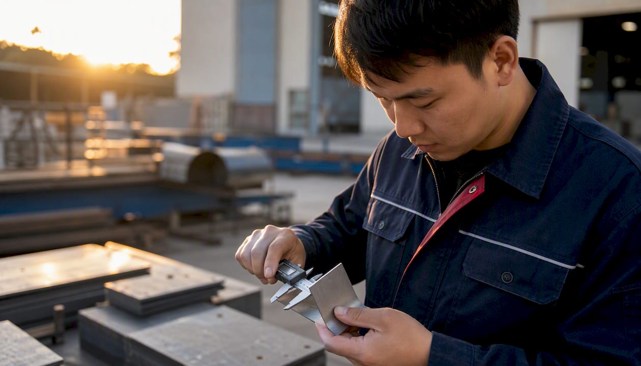
The K-factor is the ratio of the neutral axis distance from the inside surface to the material thickness, and it controls how much flat stock you need to produce a bent part at the correct final dimension. For engineers designing parts for Chinese fabricators, three actions matter before anything else: (1) lock your material grade, thickness tolerance, and tooling spec in writing; (2) request a single test coupon from the shop before committing to a production run; and (3) enter the verified K value into your CAD/CAM bend table, not the textbook default. HLH SHEET METAL runs exactly this verification workflow for US clients, returning measured bend allowance data and a signed measurement sheet so you have a documented K before the first production piece ships.
Key Takeaways
Accurate K-factor bending with Chinese fabricators requires locking material and tooling specs, verifying K with a test coupon, and entering the confirmed value into your CAD/CAM bend table before any production quantity runs.
| Point | Details |
|---|---|
| K-factor definition | K = neutral axis distance from inside surface divided by material thickness; practical range is 0.30–0.50 for press-brake work. |
| Core BA formula | BA = (π / 180) × A × (R + K × T); use consistent units and verify the angle convention in your CAD software. |
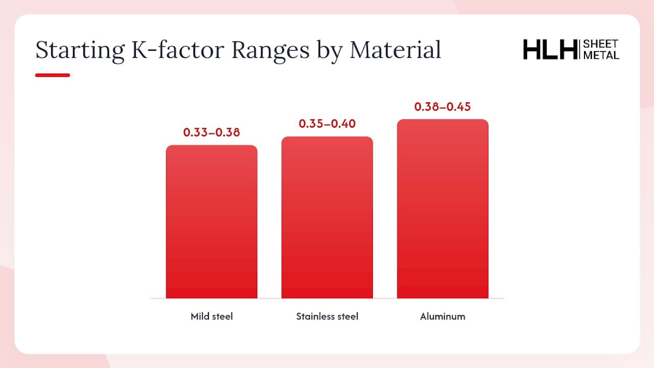
| Starting K values | Mild steel air bends start at 0.33–0.38; stainless at 0.35–0.40; aluminum at 0.38–0.45. All require coupon verification. |
| Coupon protocol | Supply material spec, tooling spec, and coupon geometry in the RFQ; request measured BA, derived K, and a signed measurement sheet before approving production. |
| HLH SHEET METAL | Runs ISO-certified coupon verification and returns documented K data, making it a direct next step for US engineers qualifying a Chinese fabricator. |
What Does K-factor Actually Represent In A Bent Cross Section?
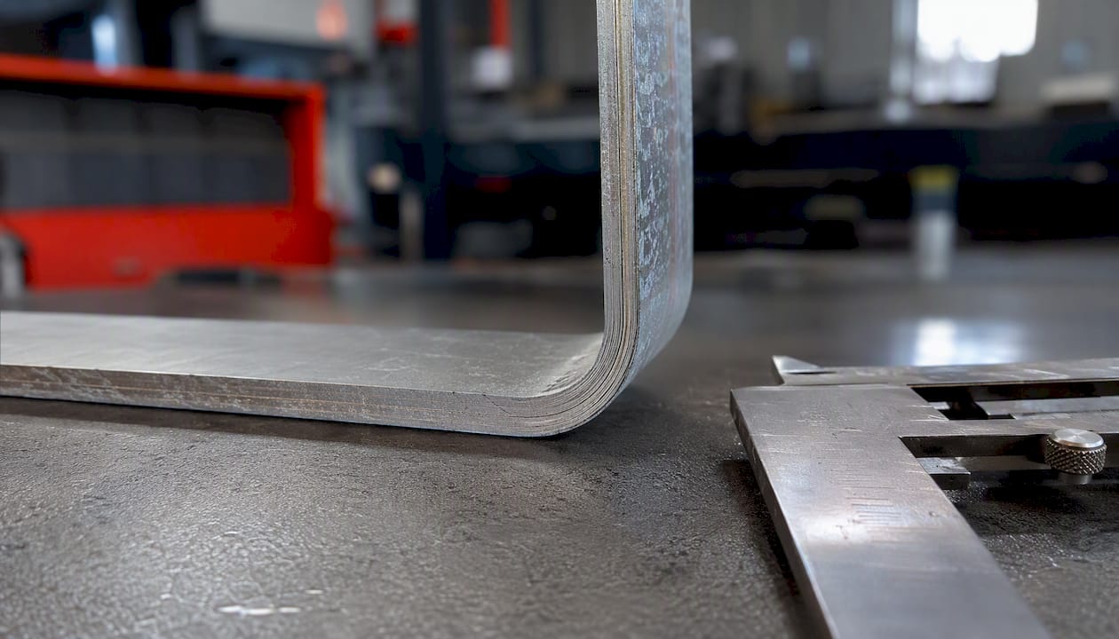
When sheet metal bends, the inside surface compresses and the outside surface stretches. Somewhere between those two zones lies a layer that neither compresses nor stretches: the neutral axis. In theory, the neutral axis sits at the geometric center of the sheet. In practice, plastic deformation pushes it toward the inside surface, which is why the neutral axis location matters for flat-pattern math.
K is defined as:
K = t / T
where t is the distance from the inside surface to the neutral axis, and T is the full material thickness. A K of 0.5 means the neutral axis is exactly centered. A K of 0.33 means it has shifted one-third of the way from the inside surface, which is typical for mild steel in air bending.
The Fabricator’s analysis of K-factor confirms that practical K values for press-brake bending fall roughly between 0.30 and 0.50, depending on material, bend radius, and method. Here is what moves that number:
- Bend radius relative to thickness (R/T): A tight radius forces more compression on the inside, pushing the neutral axis inward and lowering K. A generous radius keeps deformation mild and K closer to 0.5.
- Material ductility and temper: Softer, more ductile materials (annealed aluminum, dead-soft copper) allow the neutral axis to stay closer to center. Hard tempers and high-strength steels push it inward.
- Bending method: Air bending produces less through-thickness stress than bottoming or coining, so K tends to be higher for air bends. Coining drives K down toward 0.30 or below.
- Grain direction: Bending across the grain (perpendicular to the rolling direction) typically yields a slightly higher K than bending parallel to it, because the material resists compression differently.
- Lubrication and tooling surface condition: These affect friction at the die contact points, which changes how the material flows and where the neutral axis settles.
The Formulas You Need: Bend Allowance, Bend Deduction, And Flat Length
Bend Allowance (BA)
The core formula is:
BA = (π / 180) × A × (R + K × T)
Variables:
- A = bend angle in degrees (the angle through which the material bends, not the included angle of the finished part)
- R = inside bend radius in millimeters or inches (must be consistent with T)
- K = K-factor (dimensionless, 0.30–0.50 for most press-brake work)
- T = material thickness in the same unit as R
For a 90° bend in mild steel with a 2 mm inside radius and a typical K value, the bend allowance can be calculated using the formula BA = (π / 180) × A × (R + K × T), where A, R, K, and T are the bend angle, inside radius, K-factor, and material thickness respectively.
Rucheng Machinery’s bend allowance reference provides this formula along with starting K values and a test-coupon workflow to verify it before production.
Bend Deduction (BD) And Outside Setback (OSSB)
Outside setback is the distance from the bend tangent line to the outside mold line:
OSSB = tan(A / 2) × (R + T)
Bend deduction ties BA and OSSB together:
BD = 2 × OSSB − BA
To compute flat length from outside flange dimensions (the most common drawing convention):
Flat length = (Flange 1 outside) + (Flange 2 outside) − BD
If your drawing calls out inside dimensions instead:
Flat length = (Flange 1 inside) + (Flange 2 inside) + BA
Angle convention matters. The bend angle A in the BA formula is the angle of deformation, not the included angle of the finished part. A 90° bend in the finished part is a 90° deformation angle. A 30° flange off a flat plate is a 30° bend angle. Mixing these up is one of the most common sources of flat-pattern error, and it is invisible until the first piece arrives wrong.
Pro Tip: When entering K into SolidWorks, CATIA, or Inventor, confirm whether the software expects the deformation angle or the included angle. SolidWorks Sheet Metal uses the deformation angle by default; some older CAM post-processors use the supplement. Check the software documentation once and note it in your CAD template.
The Aivon comparison of K-factor vs. bend allowance explains when to enter K directly versus when to enter measured BA: K works well for quick CAM programming and early DFM; measured BA is preferable for proven, tight-tolerance production runs where the shop has already characterized the tooling.
Starting K-factor Values By Material And Bend Method
These are nominal starting points. Every shop has its own tooling inventory, V-die openings, and press-brake characteristics, so treat these as first-article programming values only. Verify with a test coupon before releasing to production.
For thin sheet in the 0.5–1.5 mm range, a default K of 0.33–0.40 is generally safe as a starting point. WUSVEK’s bending guide notes that as thickness climbs above roughly 3 mm, or when bottoming and coining are used, K-based estimates diverge enough that measured BA becomes the more reliable input.
Pro Tip: Tag every K value in your CAD/CAM material library with three fields: material grade, V-die opening, and punch nose radius. A K of 0.38 for 5052-H32 on a 10 mm V-die is not the same as 0.38 for the same material on a 6 mm V-die. Without those tags, the value is almost meaningless when a different shop or a different operator picks up the job.
What Moves K In Practice: Variables To Control And Document
Understanding the formula is the easy part. Keeping K stable across a production run is where most tolerance failures originate. Each variable below can shift your actual K by 0.02–0.05, which translates directly into flat-pattern error.
- Material grade and temper: Substituting 5052-H32 for 5052-H34 mid-run changes yield strength and ductility enough to shift K measurably. Specify the full ASTM designation on the drawing, not just “aluminum.”
- Thickness tolerance: Sheet metal thickness varies within a coil. A nominal 2 mm sheet may run 1.85–2.15 mm. Since K × T appears in the BA formula, a 0.15 mm thickness swing at K = 0.38 changes BA by roughly 0.06 mm per bend, which compounds across multiple bends.
- Inside radius (R/T ratio): As R/T drops below 1, the neutral axis shifts inward sharply and K drops. As R/T rises above 3, K approaches 0.5. Specifying a minimum inside radius on the drawing is not just a cracking concern; it directly controls which K value is valid.
- V-die opening: A wider V-die produces a larger effective bend radius, raising K. Shops often select V-die opening as 6–10× material thickness, but the exact choice is theirs unless you specify it. Specify it.
- Punch nose radius: A sharp punch nose concentrates stress and drives K down. A radiused punch distributes it. If you need a specific inside radius, call out the punch nose radius or the required inside radius directly.
- Bending method: Air bending, bottoming, and coining produce different K values for the same material and tooling. Air bending is the most common and gives the highest K; coining the lowest. State the required method on the drawing or in the RFQ.
- Back-gauge accuracy: Inconsistent back-gauge positioning shifts where the bend lands relative to the flat pattern, producing flange-length errors that look like K errors. Ask the shop to confirm back-gauge repeatability.
- Grain direction: For aluminum and some steels, bending parallel to the rolling direction increases cracking risk and can lower K slightly. Call out grain direction when it matters.
- Springback: Springback is not K, but it interacts with K measurement. If the shop over-bends to compensate for springback, the measured angle at the coupon may not match the programmed angle, corrupting your back-calculated K.
Pro Tip: Add a tooling note block to every sheet metal drawing: “Bending method: air bend. V-die opening: [X] mm. Punch nose radius: [Y] mm. Required inside radius: [Z] mm.” This single block eliminates the most common source of K mismatch between shops.
Worked Examples: Calculating BA And Flat Length Step By Step
Example 1: Single 90° Bend
Given: 2 mm mild steel (1018), inside radius R = 2 mm, K = 0.33, flange A (outside) = 50 mm, flange B (outside) = 30 mm.
Step 1: Calculate BA
BA = (π / 180) × 90 × (2 + 0.33 × 2)
BA = 1.5708 × (2 + 0.66)
BA = 1.5708 × 2.66
BA = 4.18 mm
Step 2: Calculate OSSB
OSSB = tan(90 / 2) × (R + T) = tan(45°) × (2 + 2) = 1.0 × 4 = 4.00 mm
Step 3: Calculate BD
BD = 2 × OSSB − BA = 8.00 − 4.18 = 3.82 mm
Step 4: Flat length from outside dimensions
Flat length = 50 + 30 − 3.82 = 76.18 mm
Measurement target for the test coupon: After bending, measure flange A and flange B from the outside mold lines to the tangent points. Their sum minus the flat blank length should equal BD = 3.82 mm. Measure the inside radius with a radius gauge and confirm it matches the programmed 2 mm. Measure thickness at three points away from the bend zone.
Example 2: Multi-bend U-channel
Given: 1.5 mm stainless 304, K = 0.38, inside radius R = 1.5 mm, two 90° bends. Outside web = 60 mm, two flanges each 40 mm outside dimension.
BA per bend:
BA = (π / 180) × 90 × (1.5 + 0.38 × 1.5) = 1.5708 × (1.5 + 0.57) = 1.5708 × 2.07 = 3.25 mm
BD per bend:
OSSB = tan(45°) × (1.5 + 1.5) = 3.00 mm
BD = 2 × 3.00 − 3.25 = 2.75 mm
Flat length:
Flat = 40 + 60 + 40 − 2.75 − 2.75 = 134.50 mm
Cumulative tolerance note: With two bends, any K error doubles. If your actual K is 0.40 instead of 0.38, each BA is 3.34 mm instead of 3.25 mm, adding 0.09 mm per bend. Over two bends, the flat blank is 0.18 mm short, and the finished channel is 0.18 mm too wide. At ±0.25 mm overall tolerance that is survivable; at ±0.10 mm it is not. This is why a test coupon before the production run is not optional for tight-tolerance multi-bend parts.
Bend order note: For a U-channel, bend the flanges before any secondary operations. If the part has holes near the bend zone, confirm their distance from the bend line exceeds 2T + R to prevent distortion during bending.
How To Determine The Actual K For A Specific Chinese Fabricator
Nominal K values from a chart get you close. A shop-verified K gets you there. The methodology below is repeatable and can be pasted directly into an RFQ or a vendor qualification email.
Pre-test Data To Supply To The Shop
- Material specification: full ASTM/EN grade, temper, and nominal thickness with tolerance band.
- Thickness sampling method: measure at five points across the blank width and record all values.
- Tooling specification: V-die opening, punch nose radius, and bending method (air, bottom, or coin).
- Coupon geometry: a simple L-bracket with one 90° bend, flange A = 50 mm and flange B = 50 mm (outside dimensions), flat blank = 96.18 mm for K = 0.33 in 2 mm mild steel (adjust for your material).
- Required measurements to return: actual flange lengths (outside), actual bend angle, actual inside radius, actual thickness at three points, and photographic evidence of the bent coupon next to a steel rule.
What To Measure And How To Back-calculate K
Once the coupon arrives:
- Measure actual flange A and flange B from outside mold lines.
- Compute actual BD: BD = (Flange A + Flange B) − flat blank length.
- Compute actual BA: BA = 2 × OSSB − BD, where OSSB uses the measured inside radius and thickness.
- Back-calculate K: rearrange the BA formula: K = (BA / ((π / 180) × A) − R) / T
Enter this K into your CAD/CAM material library tagged with the shop name, tooling spec, and date.
Minimal Reporting Template For The RFQ
- Measured thickness (five points, mm): ___
- Measured flange A (outside, mm): ___
- Measured flange B (outside, mm): ___
- Measured inside radius (mm): ___
- Measured bend angle (degrees): ___
- Derived BA (mm): ___
- Derived K: ___
- Tooling used (V-die opening, punch nose radius): ___
- Operator signature and date: ___
Sekkei-Tech’s DFM guide recommends establishing K empirically for each fabricator and providing flat-pattern DXFs or explicit K values in the RFQ to eliminate ambiguity. Providing the coupon geometry and the reporting template in the RFQ itself cuts the back-and-forth to a single exchange.
Pro Tip: Ask for the measurement sheet as a PDF with the operator’s name and date. This creates a traceable record you can attach to your design history file. If the part ever fails in the field and the investigation traces back to a flat-pattern error, that signed sheet is your evidence that the K was verified.
Drawing Callouts And Communication Practices For Chinese Fabricators
What To Put On The Drawing
A sheet metal drawing sent to a Chinese fabricator should include every variable that affects K validity. Missing any one of them gives the shop permission to choose, and their choice may not match your assumption.
Required callouts:
- Material grade and mill specification (e.g., “ASTM A1008 CS Type B, 2.00 ± 0.10 mm”)
- Measured thickness with sampling plan (“measure at 5 points per blank, record all values”)
- Target inside radius for each bend
- V-die opening and punch nose radius (or a note: “inside radius to be achieved by air bending with punch nose radius ≤ R”)
- Bending method: air, bottom, or coin
- Bend order (numbered on the drawing or in a bend sequence table)
- Required flat pattern K value or flat pattern DXF, clearly labeled as “for reference only” or “use as blank geometry”
Tolerance Language That Works In Practice
For single-bend parts, ±0.25 mm on overall length and ±0.5° on bend angle is achievable with a well-maintained press brake and a verified K. For multi-bend assemblies, tighten the angle tolerance to ±0.3° per bend and accept that overall length tolerance will stack; specify critical dimensions individually rather than as a chain.
Communication Practices That Reduce First-article Cycles
Sekkei-Tech’s guidance is direct: early supplier engagement and explicit flat-pattern data reduce ambiguity more than any other single action. Practically, that means:
- Attach both STEP and DXF files. STEP carries 3D geometry; DXF carries the flat pattern. Provide both.
- Include the coupon request in the RFQ, not as a follow-up. Shops that receive it upfront treat it as a standard deliverable, not an extra burden.
- Ask explicitly: “Please return measured BA, derived K, and photos of the bent coupon before proceeding to production quantity.”
- Use metric units in all drawings sent to Chinese fabricators. Inch-unit drawings are workable but introduce conversion risk.
- When emailing, number your questions. Chinese engineers respond more completely to numbered lists than to paragraph-form requests, where questions buried mid-paragraph are often missed.
Pro Tip: Send a single-page “bend spec summary” as a separate PDF alongside the full drawing package. It lists material, tooling, K, and tolerance in a table format. Shops print it and tape it to the press brake. This one page eliminates most verbal miscommunications during production.
Working with a Chinese sheet metal fabricator that has an English-speaking engineering team removes most of the translation friction, but the drawing discipline above applies regardless of who you work with.
Common K-factor Mistakes And How To Fix Them
Avoid using a single default K-factor for all materials and tooling combinations. Instead, establish a library with distinct K values per material and tooling setup, verified through test coupons before production.
Document tooling specifications clearly on the drawing. Changes in tooling, such as V-die opening, invalidate previous K values and can affect part dimensions.
Use either bend allowance (BA) or bend deduction (BD) methods consistently in flat-pattern calculations to prevent calculation errors. Mixing the two methods can lead to significant dimensional mistakes.
Measuring the wrong points on the coupon. Fix: measure outside flange lengths from the outside mold line to the tangent point, not to the edge of the material. Measuring to the edge includes the radius geometry and overstates the flange length.
Skipping the coupon test because the part “looks simple.” Fix: run the coupon. A single 90° bend in a new material on a new shop’s tooling takes 20 minutes to verify and can save a full production run. The FMA Precision Sheet Metal Council supports exactly this kind of shop-qualification practice as a standard step in precision fabrication.
Assuming K is stable across a material batch. Sheet thickness varies within a coil. If thickness drifts 0.15 mm and you do not re-measure, your BA calculation carries that error into every bend.
Quick Troubleshooting Flow
Flat length error on finished part:
- Check the bend angle first. An angle error of 1° changes the effective flange length more than a K error of 0.02.
- If angle is correct, measure the inside radius. A radius larger than specified raises BA and lengthens the flat.
- If radius is correct, back-calculate K from the measured coupon and compare to the programmed value. Update the CAD/CAM table.
- If K matches but parts are still off, check thickness at five points. Thickness variation is the most common hidden variable.
Quick-reference Tables For DFM And Quoting
Starting K Values (condensed)
| Material | Air Bend K | Bottom Bend K |
|---|---|---|
| Mild steel (1008/1018) | 0.33–0.38 | 0.30–0.33 |
| Stainless 304 | 0.35–0.40 | 0.33–0.35 |
| Aluminum 5052 | 0.38–0.45 | 0.33–0.40 |
| Copper / brass (annealed) | 0.40–0.45 | 0.35–0.40 |
| HSLA | 0.30–0.35 | 0.30–0.32 |
Recommended Minimum Inside Radius (R/T Guidance)
Formula Cheat Sheet
| Formula | Expression | Use |
|---|---|---|
| Bend allowance | BA = (π / 180) × A × (R + K × T) | Flat pattern from inside dimensions |
| Outside setback | OSSB = tan(A / 2) × (R + T) | Relates outside mold lines to bend center |
| Bend deduction | BD = 2 × OSSB − BA | Flat pattern from outside dimensions |
| Flat (outside dims) | L = F1 + F2 − BD | Most common drawing convention |
| Flat (inside dims) | L = F1 + F2 + BA | Less common; verify drawing convention |
| Back-calculate K | K = (BA / ((π / 180) × A) − R) / T | From measured coupon data |
All formulas assume consistent units throughout (mm or inches, not mixed).
How HLH SHEET METAL Verifies K-factor Accuracy For Production Runs
HLH SHEET METAL’s verification process follows the same test-and-lock methodology described in this guide, applied within their ISO-certified facilities in China.
The workflow engineers can expect:
- Thickness measurement: HLH measures incoming sheet at multiple points per blank and records actual thickness before programming the press brake.
- Tooling lock: The V-die opening, punch nose radius, and bending method are documented and held constant for the duration of the job. Tooling changes require a new coupon verification.
- Coupon bend and measurement: A first-article coupon is bent, measured for flange lengths, inside radius, and angle, and the actual BA and K are back-calculated. Results are recorded on a measurement sheet.
- CAD/CAM bend table update: The verified K is entered into the bend table for the specific material and tooling combination. Subsequent production pieces use this locked value.
- First-piece approval: The first production piece is measured against the drawing tolerances before the full run proceeds.
HLH SHEET METAL holds ISO certifications and maintains in-house QA procedures that engineers can request as part of vendor qualification. The FMA Precision Sheet Metal Council and FMA Foundation publish best-practice frameworks that align with HLH’s QA approach, giving engineers a recognized benchmark to compare against.
To request K verification from HLH SHEET METAL, send:
- Material spec and thickness tolerance
- STEP and DXF files
- Tooling preferences (or ask HLH to recommend based on your radius requirement)
- The coupon reporting template from Section 7
HLH returns measured BA, derived K, coupon photos, and a signed measurement sheet. For engineers dealing with common quality issues in Chinese sheet metal fabrication, this documented verification step is the single most effective way to prevent flat-pattern errors from reaching production.
What Moving Precision Parts To China Actually Teaches You
The conventional advice is to “communicate clearly and verify everything.” That is true but incomplete. What actually happens when you move precision sheet metal to a Chinese shop is that your drawing discipline gets stress-tested in ways a domestic shop would quietly work around.
A domestic fabricator with years of your business will call you when something looks wrong. A new Chinese vendor, especially one receiving a first order, will often bend what the drawing says, even if the drawing has an ambiguity that an experienced eye would flag. That is not a cultural failure; it is a contractual one. The drawing is the contract.
The engineers who succeed fastest with Chinese fabricators are the ones who treat the first order as a process qualification, not just a parts order. They send the coupon request in the RFQ. They specify tooling. They ask for the measurement sheet before approving production. Three actions, every time, with every new vendor:
- Send a complete drawing with tooling callouts and a coupon request embedded in the RFQ.
- Review the measurement sheet before approving production quantity.
- Store the verified K in your CAD library tagged to that vendor and tooling combination.
The engineers who struggle are the ones who send a STEP file, a delivery date, and a price target, then wonder why the parts are 0.4 mm off. The math is not the hard part. The discipline is.
HLH SHEET METAL Handles K Verification So Your First Production Run Ships Right
Getting K-factor bending right with a Chinese fabricator is faster when the shop already runs a documented verification workflow. HLH SHEET METAL does exactly that: for every new precision bending job, the team measures incoming material, locks tooling, bends a coupon, and returns a signed measurement sheet with the derived K before production begins. US engineers get English-language communication, ISO-certified QA, and a dedicated support contact who understands the tolerance expectations behind the drawing.
Whether you need a single prototype to validate your flat pattern or a full production run after K is locked, HLH SHEET METAL handles both from the same facility. Submit your STEP and DXF files and request a precision sheet metal fabrication quote to start the K verification process.
Sources
- Press Brake Bend Allowance Chart 2026: K-Factor, Formula & Flat Pattern Setup
- Analyzing the k-factor in sheet metal bending
- Sheet Metal Bending Guide: Process, Types & Materials | WUSVEK
- K-Factor vs Bend Allowance in Sheet Metal: What’s the Difference?
- Sheet Metal Design for Manufacturing: Bend Radius, K-Factor, and Flat Patterns | 設計×現場ラボ
FAQ
How Do You Calculate The K-factor In Sheet Metal Bending?
Back-calculate K from a measured test coupon using the rearranged BA formula: K = (BA / ((π / 180) × A) − R) / T, where BA is the measured bend allowance, A is the bend angle, R is the measured inside radius, and T is the measured material thickness.
What Should My K-factor Be For Most Press-brake Work?
Practical K values fall between 0.30 and 0.50 for most press-brake applications. Mild steel in air bending typically starts at 0.33–0.38; aluminum at 0.38–0.45; stainless at 0.35–0.40. Verify with a test coupon before production.
Why Is K-factor Used In Sheet Metal Design?
K-factor gives CAD/CAM software a single dimensionless input to compute accurate bend allowance and flat-pattern length across different materials, radii, and bend angles, without requiring a separate measured BA for every combination.
What Is The K-factor For A 90° Bend?
The K-factor does not change with bend angle; it is a material and tooling property. For a 90° bend in mild steel with air bending, K is typically 0.33–0.38. The bend angle (90°) enters the BA formula separately as the variable A.
When Should I Use Measured Bend Allowance Instead Of K-factor?
Switch to measured BA when thickness exceeds roughly 3 mm, when bottoming or coining is used, or when parts require tight tolerances that leave no room for K-based estimation error. As Aivon explains, most shops start with K for programming speed and transition to measured BA once a tooling combination is fully characterized.
