



Table Of Contents
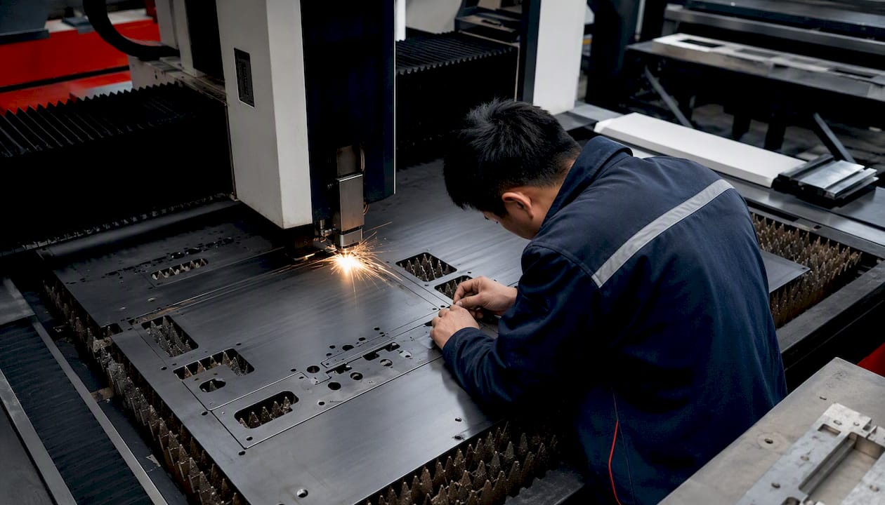
For most sheet metal work, laser cutting holds dimensional tolerances within ±0.010 in (±0.25 mm), and fiber laser systems routinely achieve ±0.05 mm on thin stock under controlled conditions. Those are the numbers worth putting in your head before you open a drawing. For noncritical geometry, a general tolerance of ±0.020 in (±0.5 mm) in the title block is a safe, cost-effective default. For mating features, holes, and slots, call out ±0.005–0.010 in explicitly on the dimension. When you need tighter than ±0.002 in (±0.05 mm) on a bearing seat or precision pin, plan for secondary machining. Laser cutting alone rarely delivers that repeatably.
Three situations where laser cutting is not the right sole process:
- Bore or pin fits requiring tolerances below ±0.05 mm (±0.002 in)
- Parts where edge hardness from the Heat Affected Zone (HAZ) would cause fatigue cracking at a bend line
- Flatness requirements tighter than approximately 0.005 in per inch of span without a secondary straightening operation
Key Takeaways
Laser cutting holds ±0.1–0.25 mm on most sheet metal work, but the drawing strategy, not the machine, determines whether that precision translates into a functional part.
| Point | Details |
|---|---|
| Default title-block tolerance | Use ISO 2768-m or ±0.020 in for noncritical geometry; override only for mating features. |
| Critical feature callouts | Specify ±0.05–0.10 mm explicitly on holes, slots, and mating edges that affect assembly fit. |
| Minimum feature rules | Keep hole diameter and slot width at least 1× material thickness; edge distance at least 1.5× thickness. |
| Secondary machining threshold | Plan for reaming or milling when any feature requires tighter than ±0.05 mm (±0.002 in). |
| HLH SHEET METAL | Provides DFM review, ISO-certified inspection, and kerf compensation as standard services for laser-cut parts. |
What Laser Cutting Tolerances Actually Look Like By Material And Thickness
The following outlines typical achievable tolerances for common material groups and thickness bands. These reflect real shop capability, not machine-spec marketing numbers.
Tolerance capability tends to be tighter with thinner material and loosens with thicker plate., and edge taper becomes a visible quality issue above roughly 10 mm.
Kerf width by laser type:
Fiber lasers produce a kerf of approximately 0.006–0.012 in (0.15–0.3 mm); CO2 lasers run wider at roughly 0.008–0.020 in (0.2–0.5 mm), with thicker material and higher power pushing toward the upper end of both ranges. Nesting and CAM software typically compensates for kerf automatically, but when tolerances are tight, confirm the shop’s compensation value matches your nominal geometry.
Fiber laser systems can achieve positional accuracy around ±0.05 mm in fine settings, with ±0.1 mm serving as a reliable general shop target for thin sheet applications. Both values map to ISO 2768 fine and medium grades, which is the most practical way to reference them on a drawing.
Factors That Tighten Or Loosen Dimensional Control
No single variable controls laser cutting precision. It is a combination, and understanding each one lets you predict where your drawing’s tolerance callouts are at risk.
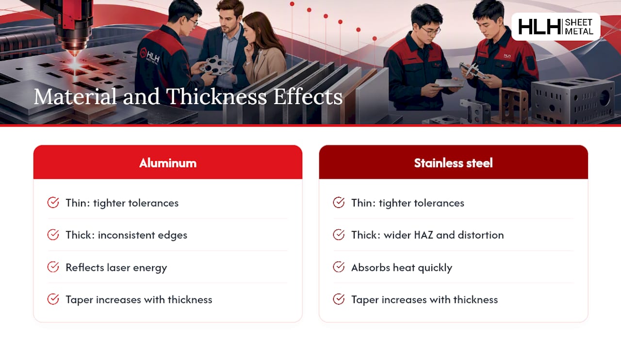
Material type and thickness are the biggest levers. Aluminum reflects more laser energy than steel, which can cause inconsistent cut edges at higher thicknesses. Stainless steel builds heat quickly, increasing HAZ width and potential distortion. Thicker stock relaxes achievable tolerances because the beam must travel further through material, and the cut edge develops more taper.
Machine calibration and focus matter more than most designers realize. A fiber laser running with a slightly defocused beam or worn nozzle can drift 0.1–0.2 mm from nominal without any visible alarm. Shops that run high-volume production recalibrate on a schedule; job shops may not. Ask.
Fixture and nesting strategy directly affect positional accuracy. Unsupported sheet that flexes during cutting introduces positional error that no amount of machine precision can recover. Parts nested near the sheet edge or cut in a single pass with no intermediate support are more vulnerable.
Part geometry is often overlooked. Long, thin features (narrow brackets, thin webs) accumulate thermal distortion along their length. Small holes near each other or near an edge concentrate heat, which can cause the hole to go slightly oval or the edge to bow. The CMU design-for-manufacture exercises illustrate exactly this kind of feature interaction.
Thermal distortion and residual stress are the hardest to predict. Laser cutting is a thermal process. The HAZ changes local hardness and can leave residual stresses that cause the part to spring slightly after cutting. For fatigue-critical parts, avoid placing bend lines at cut edges where HAZ hardness changes are concentrated.
Pro Tip: If your part has tolerances tighter than ±0.1 mm on more than a few features, ask the supplier for a process capability study (Cp/Cpk data) rather than relying on a shop’s general tolerance claim. A Cpk above 1.33 on the critical dimension tells you the process is genuinely capable, not just occasionally lucky.
Design Rules For Holes, Slots, Tabs, And Edge Distance
These are the minimums that keep rework rates low. They come from shop-level design guides and are consistent with what experienced fabricators request during DFM review.
Holes:
- Minimum diameter: equal to material thickness (1× t), with 1.5× t preferred for reliable roundness
- Press-fit holes: specify ±0.05 mm or tighter and plan for reaming; laser alone is not repeatable enough for interference fits
- Slip-fit holes: ±0.1–0.15 mm is achievable on thin stock; add clearance to the nominal diameter to account for kerf
Slots:
- Minimum width: 1× material thickness; narrower slots trap heat and produce tapered walls
- Slot length-to-width ratio: keep below 5:1 for thin sheet; longer slots in thicker material tend to bow
Edge distance and feature spacing:
- Minimum distance from a hole or slot center to the part edge: 1.5× material thickness
- Feature-to-feature spacing (hole center to hole center, or slot to slot): at least 2× material thickness to avoid heat buildup between features
Tabs for nesting:
- Tab width: at least 3 mm, or 2× material thickness, whichever is larger
- Tab spacing: no more than 250 mm apart for parts over 300 mm in any dimension
For threaded hardware holes, laser-cut the clearance hole to the thread’s minor diameter plus 0.2–0.3 mm, then tap or use a press-in insert. Trying to laser-cut a thread-ready hole to exact minor diameter is asking for tolerance trouble.
How To Write Tolerances On Engineering Drawings For Laser Cutting
The most common drawing mistake is applying a single tight tolerance across every dimension. Specifying tolerances tighter than ±0.010 in materially increases cost, and most features on a laser-cut part do not need it.
Title block general tolerance:
Use ISO 2768-m as the default general tolerance for most laser-cut sheet metal work. It covers linear dimensions up to 2000 mm with tolerances ranging from ±0.1 mm on small features to ±0.5 mm on larger spans, which aligns well with what a well-maintained fiber laser can hold. If your shop works in imperial units, a title-block note reading “UNLESS OTHERWISE SPECIFIED: ±.020 IN” covers noncritical geometry without over-constraining the job.
Feature-level callouts:
- Apply explicit tolerances only to mating features, fastener holes, and any dimension that affects assembly fit or function
- Use three decimal places (e.g., 12.500 ±0.050 mm) for critical features; two decimal places (e.g., 12.50 ±0.20 mm) for general geometry
- Avoid four decimal places on laser-cut dimensions. It implies a precision the process cannot reliably deliver and creates unnecessary inspection burden
Kerf and orientation notes:
- Add a drawing note specifying the nominal kerf value if the shop’s compensation is critical to your geometry: “NOMINAL KERF: 0.20 MM — CONFIRM COMPENSATION WITH SUPPLIER BEFORE PRODUCTION”
- For asymmetric parts where grain or burr direction matters, note the required cut orientation
- When providing DXF files, confirm whether the file represents the nominal part outline or the compensated cut path; mismatches here cause systematic dimensional errors
Inspection Methods, Flatness Expectations, And When To Choose Secondary Machining
Inspection by tolerance band:
- ±0.5 mm and looser: calipers and a surface plate are sufficient for most features
- ±0.1–0.5 mm: digital calipers, optical comparators, or a vision system; spot-check sampling is standard
- ±0.05–0.1 mm: optical comparator or CMM for critical features; 100% inspection on mating dimensions
- Tighter than ±0.05 mm: CMM inspection is required, along with fixture tooling to hold the part consistently during measurement
Flatness rules of thumb:
Sheet metal flatness after laser cutting degrades with part size and material thickness. A practical rule: expect approximately 0.005 in of bow per inch of span without secondary straightening. Thin aluminum and stainless steel are the worst offenders because they conduct heat unevenly. For enclosures or panels where flatness matters for sealing or assembly, specify a flatness callout on the drawing and discuss it with the supplier before quoting.
When to choose secondary operations or a different process:
- Reaming: any hole requiring a tolerance tighter than ±0.05 mm (±0.002 in) for a press or slip fit should be laser-cut undersized and reamed to final diameter
- Milling or grinding: edge features requiring tight parallelism or perpendicularity, or surfaces that need a specific Ra finish, need secondary milling or grinding after laser cutting
- Waterjet cutting: for materials sensitive to HAZ (titanium, certain composites, hardened steel), waterjet eliminates thermal effects entirely and can hold tolerances comparable to laser on thin stock
- CNC punching/stamping: for high-volume parts with simple geometry where hole location repeatability is critical, punching often outperforms laser on positional consistency
- CNC machining: when tolerances below ±0.05 mm are required on multiple features simultaneously, CNC machining is the right process from the start, not a fallback
What To Ask A Laser-cutting Supplier Before You Send The Job
A capable supplier should be able to answer these questions without hesitation. If they cannot, that tells you something.
Capability checklist to request:
- Typical positional tolerance for your material and thickness (not just the machine spec)
- Kerf value used for your material and the compensation method in their CAM/nesting software
- Machine type and model (fiber vs. CO2, wattage, bed size)
- Fixture and clamping approach for thin or large-format sheet
- Calibration frequency and most recent calibration records
QA artifacts worth requesting:
- Sample first-article inspection report (FAIR) for a similar part
- Cpk data if your tolerances are tighter than ±0.1 mm on critical features
- Material certificates (mill certs) for traceability
- ISO certification documentation — ISO-certified manufacturers maintain documented quality systems that make these requests routine, not exceptional
Pro Tip: Ask the supplier to cut a sample of your most tolerance-critical feature in your actual material before committing to production quantities. A $50 sample run that reveals a kerf compensation issue saves far more in rework costs downstream.
HLH SHEET METAL’s laser cutting services include DFM review, material-specific kerf compensation, and sample inspection reports as standard parts of the quoting process. Their ISO-certified QA system means the capability documentation above is already in place.
The Tolerance Strategy Most Designers Get Wrong
Most tolerance errors on laser-cut parts are not about the machine. They are about the drawing.
Designers routinely apply tight tolerances to every dimension on a part because it feels safer, or because the CAD model was dimensioned at four decimal places and no one changed it before sending the DXF. Tighter tolerances cost real money in inspection time, scrap rate, and supplier qualification, and most of those tight callouts are protecting geometry that has no functional consequence if it varies by half a millimeter.
The smarter approach: identify the two or three dimensions that actually control fit, function, or assembly, and apply tight tolerances only there. Everything else gets the general title-block tolerance. This is not a compromise. It is how parts are designed for manufacture.
Consider a steel bracket with a bearing seat. The bearing bore needs ±0.025 mm and gets a ream callout. The four mounting holes need ±0.1 mm for bolt clearance. The overall envelope dimensions need ±0.5 mm. That is three tolerance tiers on one part, each matched to its actual function. The laser cuts the bracket and the rough bore; a reamer handles the seat. Total cost is lower than specifying ±0.025 mm everywhere and sending the whole part to a CMM.
Early DFM review with your supplier is where this kind of tolerance strategy gets validated against actual shop capability, not after the first article fails inspection.
HLH SHEET METAL: From Drawing To Verified Part
Tight tolerances on paper mean nothing without a supplier who can prove capability before production starts. HLH SHEET METAL combines fiber laser cutting, in-house secondary machining, and ISO-certified inspection under one roof, so DFM review, kerf compensation, and first-article reports are part of the standard workflow, not add-on services. Their multi-plant capacity in China handles both prototype runs and high-volume production with fast turnaround, and their English-speaking engineering team can review your drawing and flag tolerance risks before a single sheet is cut.
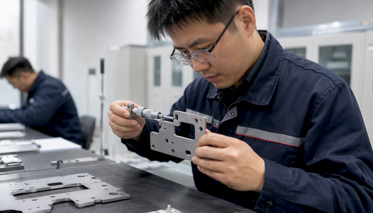
To get a DFM review or a capability statement for your next laser-cut part, request a quote or review HLH SHEET METAL’s full fabrication capabilities.
Sources
- Laser tolerances: engineers specify them and they are costing money
- Sheet Metal Design, Mechanical Tolerances and Overview | Engineers Edge
- Laser Cutting Tolerances: What to Expect and How to Design for Them | RivCut
- 2.1.28. Exercise: Laser Cutting Features and Tolerances | CMU course material
FAQ
What Is The ISO Standard For Laser Cutting Tolerance?
ISO 2768 is the most commonly referenced general tolerance standard for laser-cut sheet metal. Grade “m” (medium) is the practical default for most laser cutting work, covering linear dimensions from ±0.1 mm on small features up to ±0.5 mm on larger spans.
How Accurate Is Laser Cutting In Practice?
Fiber laser cutting typically holds ±0.1 mm as a reliable shop target for thin sheet metal, with best-case positional accuracy around ±0.05 mm under controlled conditions. Tolerances widen with material thickness, reaching ±0.4–0.8 mm on stock above 10 mm.
How Thick Can You Cut With A Laser Cutter?
Fiber lasers commonly cut mild steel up to about 10 mm and aluminum up to about 10 mm, though dimensional tolerance and edge quality degrade noticeably above 10 mm. For thick plate where tight tolerances matter, waterjet or plasma cutting followed by secondary machining is often the better path.
What Tolerances Do TRUMPF Fiber Lasers Achieve?
TRUMPF fiber laser systems are rated for positioning accuracy in the range of ±0.05–0.1 mm, consistent with the general fiber laser capability range. Actual part tolerances depend on material, thickness, fixturing, and CAM compensation, not the machine spec alone.
When Does Laser Cutting Require Secondary Machining?
Any feature requiring a tolerance tighter than ±0.05 mm (±0.002 in), such as a bearing seat or precision pin hole, should be laser-cut undersized and finished by reaming or milling. Laser cutting alone does not deliver repeatable dimensional stability at that level.
