





Table Of Contents

Design your enclosure to IEC 60297-3-100 and EIA-310 for the base dimensions, cross-check against GB/T 19520.16-2015 for Chinese manufacturing conformity, and layer in Open Rack V3 requirements only if your project uses OpenU spacing or busbar power. That’s the standards stack. Everything else is detail.
Before you send a single drawing to a factory floor in Shenzhen or Dongguan, put this on page one of the RFQ:
- Mounting width: standardized 19-inch (482.6 mm) at the front panel, non-cumulative
- U-pitch: 44.45 mm per rack unit, with hole spacing following the 12.7 / 15.875 / 15.875 mm repeat pattern per U
- Thread standard: M6 tapped or M6 cage nut, call out which
- Grounding: continuous path under 0.1 Ω, verified per unit
- Corrosion protection: salt-spray rating referenced to ASTM B117, with pass/fail hours stated
- Thermal allowance: stated max temperature rise at rated power dissipation, not just “adequate ventilation”
Attach that list to every quote request. It forces the supplier to quote against your actual tolerance stack, not their default sheet-metal practice, and it’s the fastest way to cut the back-and-forth that stretches a four-week rack project into twelve.
Key Takeaways
Compliant 19-inch rack design in China requires mapping IEC 60297 and EIA-310 dimensions onto the specific GB/T 19520 parts your supplier will reference, then backing every tolerance with a named test standard.
| Point | Details |
|---|---|
| Lock the controlling standard | Cite IEC 60297-3-100 and the matching GB/T 19520 part number directly on the drawing title block. |
| Treat tolerances as non-cumulative | Dimension every mounting hole from a single datum, holding ±0.4 mm on critical flange spacing. |
| Separate dimensional and environmental specs | Meeting U-height standards doesn’t guarantee thermal or vibration performance; specify both. |
| Require named test deliverables | Ask for ASTM B117 salt-spray certificates, grounding resistance reports, and CB/UL 62368-1 documentation before shipment. |
| Pre-flight the RFQ with a manufacturer | HLH Sheet Metal offers DFM review and QA testing support for rack projects built across its Chinese production plants. |
What Is A 19-inch Rack, And When Should You Use One?
A 19-inch rack is a mounting frame with a 482.6 mm front-panel width and a vertical grid built from repeating 44.45 mm (1U) units, standardized so panels, chassis, and blanking plates from different manufacturers bolt into the same holes. That interoperability is the entire point. It’s why a switch built in Taiwan slides into a cabinet built in Poland without anyone redesigning a bracket.
The format still wins for servers, networking gear, industrial control panels, and most data center appliances, because the supply chain around it is enormous. Rail kits, PDUs, cable arms, blanking panels: all of it assumes 19-inch spacing. If you’re designing a product meant to live in a colocation facility or a customer’s existing server room, deviating from 19-inch means asking every buyer to special-order mounting hardware, which kills adoption fast.
Where 19-inch stops being the right answer: high-density power architectures moving toward busbar distribution instead of per-U power cords, deployments needing deeper or shallower frames than the standard allows comfortably, and hyperscale environments where Open Rack’s wider, shelf-based mounting outperforms individual rail-mounted chassis. Metric IEC 60917 enclosures also show up in European industrial control cabinets where 19-inch conventions never took hold.
The 19-inch standard didn’t survive seventy years because it’s optimal. It survived because switching costs for the entire industry are too high. Design outside it only when you have a specific mechanical or power reason, not because a slightly different pitch would be marginally cleaner on paper.
What Standards Govern 19-inch Rack Design In China?
Seven documents control almost everything that matters on a rack drawing, and each one owns a different piece of the design.
IEC 60297-3-100:2008 is the anchor document. It defines the 482.6 mm basic dimension, the full table of U-heights from 1U through 12U or higher, mounting-hole positions, and the two recognized mounting-grid types. If you cite one standard on a drawing, it’s this one.
EIA-310 (commonly referenced as EIA-310-D in practitioner literature) is the North American equivalent, expressed in imperial units. It defines the same 19-inch panel width and the same hole-spacing logic but in inches rather than millimeters, and most EIA-310 guidance engineers reference maps cleanly onto the IEC metric values. The two rarely conflict on core dimensions; they conflict on how the numbers get rounded, which matters once you’re chasing ±0.4 mm tolerances.
For manufacturing inside China, GB/T 19520.16-2015 is the domestic implementation of that same 482.6 mm series. It’s the document your Chinese supplier’s quality team will actually pull off the shelf, and citing the GB/T part number directly on your drawing (not just “IEC compliant”) removes a common source of approval delays. The GB/T 19520 family branches further: GB/T 19520.22-2023 covers residential rack applications, while GB/T 19520.18-2018 handles adaptation between 19-inch equipment and metric 25 mm modular systems, a scenario you’ll hit constantly when mixing European IEC 60917 subracks into a 19-inch frame.
If your project touches hyperscale or Open Compute deployments, the Open Rack Base Specification Version 3 governs OpenU spacing, busbar interfaces, and grounding.
Environmental and mechanical testing sits outside all of the above, under IEC 61587, which specifies the vibration, shock, and climatic test methods a rack assembly must survive. Electrical safety runs through IEC/EN/UL 62368-1, the audio/video and IT equipment safety standard that replaced the older 60950 family. Corrosion testing draws from ASTM B117 (salt spray exposure) and ASTM D610 (rating rust on painted surfaces), both referenced directly in the Open Rack spec’s grounding-surface requirements.
| Standard | Governs | Where it applies |
|---|---|---|
| IEC 60297-3-100 | Base 482.6 mm dimensions, U-heights, hole patterns | All 19-inch drawings, primary reference |
| EIA-310 | Imperial-unit equivalent dimensions | North American interoperability checks |
| GB/T 19520.16-2015 | Chinese conformity, same series | Domestic supplier QC and RFQs |
| GB/T 19520.18-2018 | Metric/19-inch adaptation dimensions | Mixed subrack/chassis designs |
| Open Rack V3 | OpenU spacing, busbar, grounding | Hyperscale/OCP-aligned projects |
| IEC 61587 | Mechanical and environmental tests | Vibration, shock, climatic qualification |
| IEC/EN/UL 62368-1 | Electrical and fire safety | Certification and CB reports |
| ASTM B117 / D610 | Salt-spray corrosion testing | Finish and grounding-surface validation |
Call out edition years on drawings. GB/T standards get revised more frequently than most engineers expect, and a supplier quoting against a superseded edition of GB/T 19520 will build to different tolerance rules than you intended.
Critical Dimensions And Tolerances For 19-inch Enclosures
Every 19-inch rack drawing lives or dies on three numbers: 482.6 mm front width, usable internal clearance (typically 450 to 465.1 mm depending on rail configuration and which spec you’re following), and the 44.45 mm U-pitch that repeats up the frame.
The U-pitch isn’t a single hole spacing, it’s a three-hole repeating pattern. Within each 44.45 mm unit, the standard mounting-hole positions follow a 12.7 mm / 15.875 mm / 15.875 mm vertical sequence (some references express this as 12.7 / 7.9 / 31.75 depending on which reference point you measure from). Get this pattern wrong across a multi-U panel and the cumulative error compounds until your top mounting screw misses the rail entirely, even though every individual hole measured “close enough” on its own.
That’s exactly why IEC 60297-3-100 specifies tolerances as non-cumulative. Each hole position is measured from a fixed datum, not from the previous hole. A tolerance of ±0.4 mm on flange-hole spacing, the figure GB/T 19520.18-2018 recommends for critical mounting features, means every hole stays within that window relative to the datum edge, regardless of how many U’s stack above it. Call it out that way on the drawing, explicitly labeled “non-cumulative,” or a CNC punch program written against sequential dimensioning will drift.
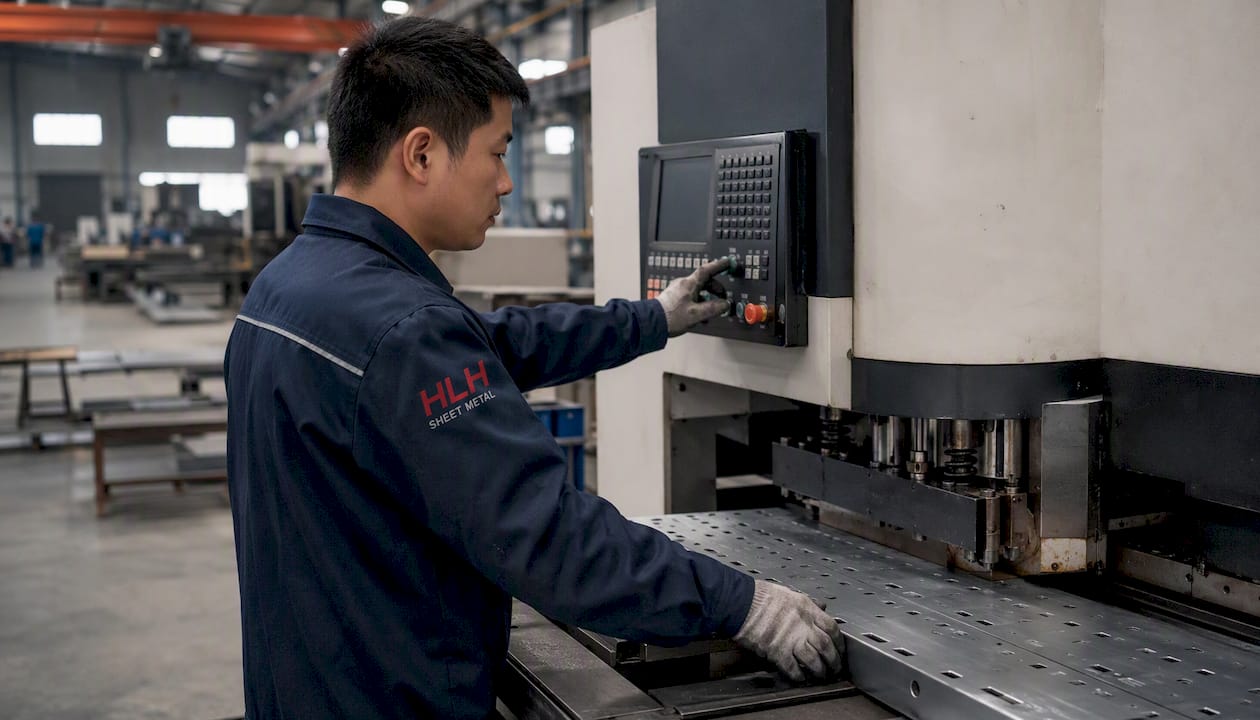
Pro Tip: In your CAD model, dimension every mounting hole from a single datum line at the base of the rail, never from hole to hole. This one habit prevents almost all of the “stacked tolerance” failures that show up during first-article inspection on multi-U assemblies.
For thread preference, metric M6 threaded fasteners or cage nuts are commonly used for mounting in modern 19-inch equipment that lets the mounting point self-align during installation. Cage nuts also tolerate the inevitable minor variance in punched hole size better than a tapped thread does, which matters more in Chinese sheet-metal production runs where multiple press operators may run the same job across a production week.
Every one of those values is a direct multiple of 44.45 mm. If a supplier’s drawing shows anything else, even a rounding to 44 mm flat, it will not stack correctly against a standard 12U cabinet, and you’ll find out during final assembly rather than during design review.
How Does Open Rack V3 Change Your Enclosure Design?
Open Rack V3 is not a variant of the 19-inch standard, it’s a different mounting philosophy, and you should only design to it when your project specifically targets Open Compute Project deployments or hyperscale data center customers who’ve standardized on it.
The most consequential difference is vertical pitch. Where EIA-310 and IEC 60297 lock you to 44.45 mm, Open Rack V3 supports a 48 mm OpenU spacing as an alternative grid. That’s not a rounding difference, it’s a genuinely different mounting interface, which means chassis designed for OpenU will not drop into a standard 19-inch rack and vice versa without an adapter.
Power delivery is the second major departure. Open Rack V3 defines centerline busbar geometry with nominal voltage options around 48V, 51V, and 54V, moving power distribution off individual power cords and onto a shared bus that runs the height of the rack. If your enclosure needs to interface with that busbar, your connector and trace sizing has to match the spec’s minimum continuous current ratings for both the power and ground return paths, not just whatever your existing power-entry module happens to support.
Key differences to design around:
- OpenU vertical pitch (48 mm) versus EIA/IEC pitch (44.45 mm), non-interchangeable without an adapter bracket
- Busbar interface geometry and voltage class (48V/51V/54V nominal), which dictates connector selection
- Power-sense lines that require dedicated signal pins separate from the main power path, used for hot-swap arc prevention
- Grounding continuity requirements tied directly to corrosion protection, referencing ASTM D610 and ASTM B117 for surface rust grading
Pro Tip: If you’re not certain a project will end up in an Open Rack deployment, design the chassis to standard 19-inch dimensions and treat OpenU compatibility as a bracket-level accessory. Retrofitting a 44.45 mm design onto a 48 mm grid is a solved problem with adapter rails. Going the other direction usually means a full chassis redesign.
What Electrical And Thermal Specs Belong On The Drawing?
A rack that satisfies every dimensional standard can still fail in the field if nobody calculated whether the enclosure can shed the heat its contents generate. Dimensional compliance and thermal/environmental adequacy are separate problems, and treating the first as a proxy for the second is one of the more expensive mistakes design teams make.
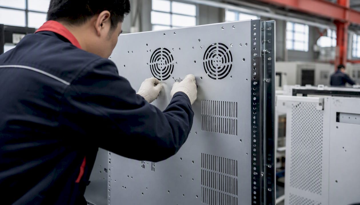
Start with power delivery. State the input voltage range explicitly, and if the project touches Open Rack, specify which busbar voltage class (48V, 51V, or 54V nominal) the enclosure’s power-entry hardware must accept. Match connector current ratings to the actual power shelf or PDU the customer will use, not a generic “rated for 20A” placeholder that may not reflect real continuous load.
Thermal planning follows a simple template you can reuse across projects: take the sum of rated power dissipation for every component in the enclosure, subtract expected efficiency losses that leave as heat elsewhere, and calculate the airflow (in CFM) needed to hold internal temperature rise within your target delta, typically 10 to 15°C above ambient for standard IT equipment. Then check that your ventilation cutouts and fan placement actually deliver that CFM without recirculating hot exhaust back into the intake, a failure mode that shows up constantly in densely packed 1U and 2U chassis. Standards bodies are consistent on this point: dimensional conformity alone doesn’t guarantee reliability, you need site-specific thermal and vibration data layered on top.
Certificates to request from any Chinese supplier before production release:
- CB test report or UL listing referencing IEC/EN/UL 62368-1 for the safety of the overall electronic equipment
- RoHS and REACH declarations covering every material and finish, not just the primary structural metal
- UL94V-0 flammability rating documentation for any plastic components, connectors, or cable management parts
None of these substitute for the others. A UL 62368-1 report covers electrical and fire safety of the system; it says nothing about whether your finish meets RoHS restricted-substance limits.
What IP, Seismic, And Corrosion Ratings Should You Specify?
Mechanical and environmental requirements are the section most first-time China-manufacturing engineers underspecify, usually because their domestic supplier “just knew” what was expected and a new Chinese vendor has no such context.
Start with the ingress protection rating. Indoor data center or office deployments typically call for IP20, protecting against finger contact and larger debris but not against dust or water. Industrial floor environments, outdoor cabinets, or anything exposed to washdown or airborne particulate needs to move up to IP54 or higher, and that decision changes your door seal design, cable gland selection, and ventilation approach.
- Set the target IP rating based on deployment environment, not a generic default, and state the test method used to verify it.
- Specify vibration and shock test levels referencing IEC 61587, which defines the mechanical and climatic test procedures for rack-mounted equipment.
- Define seismic bracing requirements if the deployment region has known seismic risk; this typically means specifying floor anchor points and cabinet base reinforcement, not just relying on stabilizer feet.
- Require salt-spray corrosion testing per ASTM B117 on any exposed metal surface, with a stated pass/fail duration.
- Specify handling and installation features: stabilizer feet or brackets that prevent tip-over during equipment installation, and ramp entry/exit angles shallow enough (commonly under 15 degrees) that a loaded cabinet can be rolled without excessive force or tipping risk.
Practical guidance from large-scale deployments, including rack planning documentation from CERN, consistently flags door clearance and cable routing space as areas where pure dimensional standards leave gaps. A rack that’s compliant on paper but has 200 mm of rear clearance in a room with 180 mm of aisle space is a field problem nobody catches during design review.
Acceptance criteria you can paste directly into a purchase order:
- Salt spray: no red rust visible after 48 hours of exposure per ASTM B117, with photographic documentation
- Vibration: no fastener loosening or panel deformation after IEC 61587 test cycle, verified by post-test dimensional check
- Load test: cabinet supports rated static load with less than 2 mm deflection at any mounting rail
Designing For Chinese Sheet-metal Fabrication
Standards tell you what the finished part must measure. They don’t tell you how a Chinese sheet-metal shop actually produces it, and that gap is where most rework originates.
Material selection depends heavily on the load case. Rack frames and structural uprights typically call for cold-rolled steel at 1.5 to 2.0 mm thickness for standard server-class loads, moving up to 2.5 mm or heavier gauge steel for equipment bays carrying substantial static weight. Door and panel components can usually drop to 1.0 to 1.2 mm since they’re not load-bearing, which saves material cost without compromising structural integrity. Finish selection follows the environmental spec: galvanized steel or powder coat over passivated steel for standard indoor corrosion resistance, and for plastics used in cable management clips, bezels, or blanking inserts, source material pre-rated to UL94V-0 rather than hoping a generic ABS supplier’s certificate holds up under audit.
Fabrication constraints that shape a good drawing:
- Minimum bend radius scales with material thickness, generally about equal to material thickness for mild steel; specifying a radius tighter than that invites cracking at the bend line
- Laser-cut kerf typically runs 0.1 to 0.2 mm depending on material and thickness, and needs to be accounted for in hole diameter tolerancing, not treated as negligible
- Spot-weld allowance requires roughly 15 to 20 mm of flat flange material around the weld point for a reliable joint
- Cage-nut mounting holes need clean, deburred edges at the specified diameter (commonly 9.5 mm square punch for standard cage nuts) since an oversized or ragged hole lets the cage nut rattle loose over time
Pro Tip: Ask your fabricator for their standard punch and die inventory before finalizing hole sizes. A hole diameter that’s 0.3 mm off their existing tooling often triggers a custom tool charge and a scheduling delay that has nothing to do with your design’s quality, it’s purely a tooling-availability issue. Matching common tooling sizes where the design tolerance allows it is one of the cheapest changes you can make to a quote.
What Belongs In A Supplier-ready Drawing Package?
A drawing set that’s technically complete but missing context items still generates clarification emails, and every one of those emails costs a day or more once you factor in time zone lag between most Western engineering teams and Chinese production floors.
Minimum drawing set:
- Front, rear, side, and exploded assembly views, dimensioned independently rather than relying on the reader to infer missing views
- Hole callouts with explicit tolerance zones, not just a nominal position
- Material specification and finish callout on every distinct part, including fastener plating
- Weight and center-of-gravity notes, especially for tall cabinets where tip-over risk during shipping or installation matters
BOM line items to include beyond the obvious sheet-metal parts:
- Standard fasteners specified by type: M6 cage nuts for rail mounting, M5 for accessory and bracket hardware
- Grounding hardware, including star washers or grounding straps and their material (typically bare copper or plated steel)
- Busbar kit references if the project touches Open Rack power architecture
- Plastic components with their UL94 rating stated directly on the BOM line, not buried in a separate material spec
Inspection points to require before the supplier ships: a dimensional inspection report against your drawing tolerances, a grounding resistance test result, a salt-spray certificate if corrosion protection was specified, and a paint adhesion test (commonly a cross-hatch tape test) for powder-coated finishes. Don’t overlook packaging and shipping constraints either. A fully assembled 42U cabinet may not fit through a standard interior doorway, and crate dimensions need to account for both the shipping container’s internal clearance and the receiving site’s loading dock and doorway measurements.
What Tests Should You Require Before Shipment?
The tests you specify on a purchase order are the only leverage you have once a production run is already underway, so vague language here costs money later.
Minimum test set for any 19-inch rack production run:
- Dimensional inspection with a full measurement report, not a spot-check summary
- Grounding continuity and resistance measurement at every bonded point
- Salt-spray or equivalent corrosion verification per ASTM B117, with duration matched to the deployment environment
- Structural load test confirming the frame holds rated static load within your specified deflection limit
- Any additional IEC 61587 mechanical tests called out in your spec, such as vibration or shock cycling
Acceptance-criteria language you can drop directly into a PO: “All flange hole centers shall measure within ±0.4 mm of nominal per drawing datum. Grounding path resistance shall measure less than 0.1 Ω at all bonded points. Salt-spray testing per ASTM B117 shall show no red rust after 48 hours exposure.” That level of specificity removes the ambiguity that lets a supplier interpret “adequate corrosion resistance” however is cheapest for them.
Deliverables to require before final payment release: full test reports for every item above, material certificates confirming alloy and thickness, RoHS and REACH declarations, photographs of the actual test setups (not stock images), and a photo of the final packed unit as it will ship. That last item sounds minor. It’s the single fastest way to catch a packaging error before a $40,000 rack order arrives with a cracked door panel.
What Factories Notice Most Often, And How To Avoid It
The drawings that cause the most trouble on a factory floor aren’t the complex ones. They’re the ones with a single ambiguous tolerance call or a missing finish spec, because that single gap forces a stop-and-clarify cycle that can delay an entire production run by a week or more while emails cross time zones.
The most common pattern: a hole pattern dimensioned correctly but with no stated tolerance class, leaving the operator to guess whether ±0.1 mm or ±0.5 mm was intended. The second most common: a finish callout that says “black finish” without specifying powder coat versus anodize versus paint, three processes with different costs, different masking requirements, and different corrosion performance. The third: no handling or packaging note at all, which means a cabinet gets crated the same way regardless of whether it’s shipping domestically or across an ocean.
The fix isn’t more drawing pages, it’s more precision on the pages you already have. Every dimension gets a tolerance class. Every finish gets a named process, not a color description. Every BOM line for a fastener states the exact standard (M6, ISO metric, cage nut type) rather than a generic part description. A consolidated BOM with one line per unique part number, cross-referenced to the drawing, catches duplicate or conflicting fastener specs before they reach the shop floor rather than after. Building a test list into the RFQ itself, rather than negotiating it after quoting, also keeps quality expectations aligned with price from day one.
Manufacturing Standards-compliant Racks With HLH Sheet Metal
Getting a rack design from CAD file to a compliant, shippable enclosure means finding a fabricator who reads IEC and GB/T tolerances correctly the first time, not after a failed first article. HLH Sheet Metal runs multiple manufacturing plants across China set up specifically for that kind of precision work: laser cutting, bending, welding, and finishing for custom server rack cabinets and network cabinets built to the same 482.6 mm and 44.45 mm interfaces this article walks through.
Engage HLH on a rack project and you get DFM feedback before production starts, so tolerance conflicts and tooling mismatches get caught on the drawing instead of on the shop floor. That includes dimensional inspection reports, material certificates for RoHS and REACH conformity, and ISO-certified quality assurance carried through to global shipping. English-speaking support handles the day-to-day back and forth directly, which cuts out the multi-day email lag that turns a small tolerance question into a week of schedule slip.
If you have a rack or enclosure drawing ready, or even a rough concept that needs DFM input first, request a quote for sheet metal fabrication and get supplier-side feedback before you commit to a production run.
Useful Standards And Reference Documents
- IEC 60297-3-100:2008 — primary source for 482.6 mm dimensions, U-height tables, and mounting-hole patterns
- GB/T 19520.16-2015 — Chinese conformity standard mirroring the IEC 60297 basic series
- GB/T 19520.18-2018 — adaptation dimensions for metric and 19-inch cross-compatibility, with recommended tolerances
- GB/T 19520.22-2023 — Chinese residential rack requirements, mapped to IEC 60297-3-110
- Open Rack Base Specification Version 3 — OpenU spacing, busbar power interfaces, and grounding/corrosion requirements
- IEC 61587 — mechanical and environmental test methods for rack-mounted equipment
- IEC/EN/UL 62368-1 — electrical and fire safety standard for electronic equipment
- ASTM B117 / ASTM D610 — salt-spray exposure testing and painted-surface rust grading
Request current edition years for each GB/T document specifically. Chinese standards revise on a shorter cycle than most Western equivalents, and a supplier quoting against a lapsed edition builds to different tolerance rules than you specified.
Sources
FAQ
What Is The Standard Width Of A 19-inch Rack?
The front-panel mounting width is 482.6 mm, defined in IEC 60297-3-100 and mirrored in EIA-310 and GB/T 19520.16-2015 for Chinese manufacturing conformity.
What Does 1u Mean In Rack Sizing?
One rack unit (1U) equals 44.45 mm of vertical height, and every standard rack height from 1U to 12U and beyond is a direct multiple of that figure.
Do I Need To Follow Open Rack V3 For A Standard Server Enclosure?
No. Open Rack V3 applies only when your project targets hyperscale or Open Compute Project deployments using 48 mm OpenU spacing and busbar power; standard 19-inch designs follow IEC 60297 and EIA-310 instead.
Which Chinese Standard Should I Cite For Rack Manufacturing Conformity?
Cite GB/T 19520.16-2015 for basic dimensional conformity, and reference GB/T 19520.18-2018 if your design needs metric-to-19-inch adaptation dimensions.
What Tolerance Should I Specify For Mounting Holes?
Specify tolerances around ±0.4 mm on flange-hole spacing, measured from a fixed datum to avoid cumulative errors, rather than sequential hole-to-hole dimensioning.
Can HLH Sheet Metal Manufacture Racks To These Standards In China?
Yes. HLH Sheet Metal fabricates custom server rack cabinets and network enclosures across its Chinese production plants, with DFM review, dimensional inspection, and material certification aligned to IEC and GB/T requirements.

