




Table Of Contents
The K-factor is the ratio of the neutral-axis distance from the inside face of a bend to the total material thickness. In practical terms, it tells you where the material neither stretches nor compresses during forming, and that location is what drives your flat-pattern length. The bend allowance formula is:
BA = (π/180) × θ × (R + K × T)
where θ is the bend angle in degrees, R is the inside radius, T is the material thickness, and K sits between 0 and 1. Most shop defaults land in the 0.3–0.5 range, with 0.44 being a common starting point for mild steel in air bending.
The K-factor is not a material constant. It shifts with radius, thickness, forming method, and tooling geometry. Treating it as a fixed default is the single most common source of flat-pattern error in production sheet metal work.
Key Takeaways
Accurate K-factor bending requires a calibrated, material- and tooling-specific value, not a universal default, applied consistently from CAD through the press brake.
| Point | Details |
|---|---|
| K-factor definition | K = neutral-axis distance from inside face ÷ material thickness; typical range is 0.3–0.5. |
| Bend allowance formula | BA = (π/180) × θ × (Ri + K × T); every variable must be in the same unit system. |
| R/T drives K | When R/T exceeds 4, K trends toward 0.5; tight bends (R/T < 1) push K toward 0.3 or lower. |
| Empirical calibration | Back-calculate K from three test coupons using K = [(180 × BA) / (π × θ × T)] − (Ri / T) and average the results. |
| CAD input check | Confirm whether SolidWorks, PTC Creo, or your calculator expects K or Y-factor before entering a value. |
What Does K-factor Mean In Sheet Metal Bending?
Before running any bend allowance calculation, every person in the chain, from the designer in CAD to the tech at the press brake, needs to be working with the same definitions.
- Neutral axis: The theoretical plane inside the material that experiences zero strain during bending. Its distance from the inside face is t = K × T. When K = 0.5, the neutral axis sits exactly at mid-thickness; when K < 0.5, it has shifted toward the inside face due to compression.
- Material thickness (T): The full stock thickness, measured perpendicular to the sheet face. This is the T in every formula.
- Inside radius (Ri): The radius at the inside face of the bend, set by the punch tip or the die opening. Always measure or specify Ri, not the outside radius.
- Bend angle (θ): The included angle of the bend in degrees. A 90° bend has θ = 90, not 270. Some CAD packages use the complementary angle; confirm which convention your software uses before entering values.
- Apex: The theoretical intersection point of the two flat legs extended to their tangent lines. Used in outside setback (OSSB) calculations.
- Outside setback (OSSB): The distance from the apex to the tangent point on the outside of the bend. OSSB = tan(θ/2) × (Ri + T). Needed when calculating flat-pattern leg lengths from outside dimensions.
Getting these terms right before touching a formula prevents the most common unit and reference-dimension errors.
How K-factor Drives Your Bend Allowance Calculation
The bend allowance is simply the arc length traced by the neutral axis through the bend zone. Because the neutral axis sits at radius (Ri + K × T) from the center of curvature, the arc length at that radius for a bend of θ degrees is:
BA = (π/180) × θ × (Ri + K × T)
Every variable in that expression has a direct physical meaning. Ri + K × T is the neutral-axis radius. Multiply it by the arc angle in radians and you get the length of material consumed in the bend. That length is what you subtract from the total flat blank to find the leg lengths, or add to leg lengths to find the blank.
A small error in K on a 90° bend in 3 mm steel with a 3 mm inside radius can produce measurable flat-pattern error per bend. Stack four bends in a bracket and that error compounds to nearly 0.75 mm, enough to fail a ±0.5 mm tolerance callout.
Worked example:
- θ = 90°, T = 2 mm, Ri = 2 mm, K = 0.44
- BA = (π/180) × 90 × (2 + 0.44 × 2)
- BA = (3.14159/2) × (2 + 0.88)
- BA = 1.5708 × 2.88
- BA = 4.52 mm
That 4.52 mm is the material consumed in the bend zone. For a Hawk Ridge Systems worked example using similar inputs, the result aligns closely, confirming the formula is consistent across sources.
How To Calculate K-factor Step By Step
There are two directions to run this calculation: forward (BA from known K) and backward (K from measured BA). Both matter in a real shop.
Direction A: Back-calculate K From A Measured Bend Allowance
Per Omni Calculator’s K-factor tool, the rearranged formula is:
K = [(180 × BA) / (π × θ × T)] − (Ri / T)
- Form a test coupon with known tooling. Use the same punch, die, and material you plan to run in production.
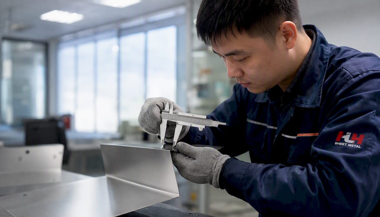
- Measure the two flat legs (L1 and L2) with calipers after forming.
- Measure the overall length of the blank before bending (Lblank).
- Compute BA = Lblank − L1 − L2.
- Measure the inside radius Ri with a radius gauge or optical comparator.
- Record θ (the actual formed angle, not the nominal).
- Plug into K = [(180 × BA) / (π × θ × T)] − (Ri / T).
Numeric example (back-calculate):
- L blank = 100 mm, L1 = 47.5 mm, L2 = 47.5 mm → BA = 5.0 mm
- θ = 90°, T = 2 mm, Ri = 2 mm
- K = [(180 × 5.0) / (π × 90 × 2)] − (2 / 2)
- K = [900 / 565.49] − 1.0
- K = 1.591 − 1.0
- K = 0.591
That result is higher than the 0.44 default, which would tell you immediately that the tooling setup or material temper is behaving differently than expected.
Direction B: Calculate BA From A Known K
- Confirm units (all mm or all inches, never mixed).
- Identify θ, Ri, T, and K from your material/tooling table.
- Apply BA = (π/180) × θ × (Ri + K × T).
- Subtract BA from the flat blank length to get usable leg lengths, or add it to leg lengths to get the required blank.
Numeric example (forward):
- θ = 120°, T = 1.5 mm, Ri = 1.5 mm, K = 0.40
- BA = (π/180) × 120 × (1.5 + 0.40 × 1.5)
- BA = 2.0944 × (1.5 + 0.60)
- BA = 2.0944 × 2.10
- BA = 4.40 mm
Unit pitfall: If your drawing dimensions are in inches and your tooling spec is in millimeters, convert everything to one system before calculating. A 0.079-inch radius entered as 0.079 mm produces a BA that is off by a factor of 25.4.
K-factor Vs. Y-factor: Which One Should You Use?
The Y-factor is a related but distinct quantity. The conversion between them is:
Y = (K × π) / 2
So for K = 0.44, Y ≈ 0.691. The Y-factor appears in DIN 6935 and some European press-brake programming systems, and it integrates the stress distribution across the bend cross-section rather than treating the neutral axis as a simple geometric line.
The Y-factor can yield marginally more precise bend allowances because it accounts for the stress gradient through the material thickness, not just the neutral-axis location. For most general fabrication work, the difference is small enough that K-factor remains the industry baseline for CAD and fabrication workflows. Where it matters is in tight-tolerance aerospace parts, deep-drawn channels, or any application where the tolerance band is tighter than ±0.25 mm per bend.
When to use Y-factor: high-precision aerospace brackets, medical device enclosures with tight assembly fits, or any job where your CAD or CNC press-brake controller explicitly asks for it. When to use K-factor: general fabrication, CAD flat-pattern generation in SolidWorks or PTC Creo, and quoting workflows where speed matters more than the last tenth of a millimeter.
Practitioners sometimes confuse the material K-factor with geometric multipliers used in outside setback calculations. Always verify whether your tool or worksheet expects the material K or a geometric factor before entering a value.
What K-factor Values Should You Use For Common Materials?
Starting K values depend on material, temper, and the ratio of inside radius to thickness (R/T). As The Fabricator’s analysis shows, when R/T exceeds about 4, the neutral-axis shift becomes negligible and K trends toward 0.5. Tight bends (R/T < 1) push K down toward 0.3 or lower.
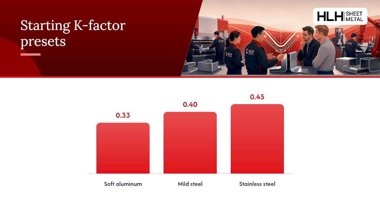
RivCut’s bend allowance calculator lists practical presets: soft aluminum near 0.33, mild steel near 0.40, and stainless steel near 0.45. These are starting points, not production values.
| R/T Ratio | Soft Aluminum | Mild Steel | Stainless Steel | Copper (soft) |
|---|---|---|---|---|
| < 1 | 0.33 | 0.33 | 0.40 | 0.33 |
| 1–2 | 0.33 | 0.40 | 0.40–0.44 | 0.40 |
| 2–4 | 0.44 | 0.44 | 0.44 | 0.40–0.45 |
| > 4 | ~0.50 | ~0.50 | ~0.50 | ~0.50 |
Use these ranges to bracket your first test bend, then measure and refine. Never pull a single number from a chart and run a production batch without a test coupon.
What Variables Change K-factor In Real Shop Conditions?
K is not a material property you look up once and file away. Several variables shift it, sometimes significantly.
- Yield strength and temper: Higher-strength alloys and harder tempers resist compression on the inside face, pushing the neutral axis outward and raising K. Annealed material compresses more freely, so K sits lower.
- Material thickness: Thicker stock tends to produce lower K values at the same R/T ratio because the strain gradient across the thickness is steeper.
- Inside radius: Tighter radii (lower R/T) drive K down. This is the single largest geometric variable.
- Forming method: Air bending, bottoming, and coining each produce different neutral-axis behavior. Air bending leaves the material partially unsupported, so K varies with tonnage and die width. Bottoming forces the material into the die, producing more consistent K values. Coining fully plastically deforms the material and tends to give the most repeatable K, though at higher tonnage cost.
- Die width: A wider V-die opening increases the effective bending radius even at the same punch tip, which raises R/T and pushes K toward 0.5.
- Punch profile: A sharp punch tip creates a tighter inside radius; a radiused tip creates a larger one. Both affect K.
- Grain direction: Bending across the grain (perpendicular to the rolling direction) typically produces a slightly higher K than bending with the grain. For aluminum and high-strength steel, this difference can be meaningful enough to warrant separate K entries in your shop table.
- Springback: Springback does not change K directly, but it changes the actual formed angle θ. If you measure θ incorrectly after springback, your back-calculated K will be wrong.
Pro Tip: When you receive a new batch of material, even from the same supplier with the same spec, run a fresh test coupon before committing to a production run. Mill certifications confirm chemistry, not the exact temper or rolling condition that affects K.
How To Measure Your K-factor Empirically In The Shop
Empirical test bends, logged per machine and material, are the standard recommended by the Fabricators & Manufacturers Association for production-grade K tables. Here is a repeatable procedure.
- Prepare test coupons. Cut at least three identical blanks from the production material lot. Recommended size: 100 mm × 50 mm (or 4 in × 2 in). Measure and record the exact blank length along the bend axis.
- Set tooling. Use the exact punch and die combination planned for production. Record punch tip radius, die opening width, and die shoulder radius.
- Form the bends. Bend each coupon at the target angle. For a 90° bend, use the same tonnage and stroke you plan to run in production.
- Measure inside radius. Use a radius gauge set or an optical comparator. Measure at three points along the bend length and average the readings.
- Measure leg lengths. Use digital calipers. Measure L1 and L2 from the tangent point of the bend to the end of each leg. Tangent points are where the flat leg meets the curved bend zone.
- Measure the actual bend angle. Use a digital protractor or angle gauge. Record the actual formed angle, not the nominal.
- Compute BA. BA = Lblank − L1 − L2.
- Back-calculate K. K = [(180 × BA) / (π × θ × T)] − (Ri / T).
- Average across coupons. Use the mean K from your three coupons as the production value. If the spread is more than ±0.02, investigate tooling consistency or material variation before proceeding.
Record the following for each test:
| Column | What to record |
|---|---|
| Material / alloy | soft aluminum |
| Thickness (T) | Measured, not nominal |
| Inside radius (Ri) | Averaged from three points |
| Punch tip radius | From tooling spec |
| Die opening | In mm or inches |
| Forming method | Air bend / bottom / coin |
| Bend angle (actual) | Measured after forming |
| Blank length | Pre-bend measurement |
| Measured BA | Computed from leg measurements |
| Calculated K | From back-calculation formula |
| Date / operator | For traceability |
Pro Tip: Repeat this procedure after any tooling change, die replacement, or when switching to a new material lot. Die wear alone can shift your effective inside radius by 0.1–0.2 mm over a production run, which moves K enough to push a tight-tolerance part out of spec.
Where Do You Enter K-factor In Solidworks, PTC Creo, And Online Calculators?
Getting the right K value into your CAD model matters as much as calculating it correctly.
SolidWorks Sheet Metal accepts a K-factor input directly in the sheet-metal feature definition. Per SolidWorks documentation, the software uses this value to compute flat patterns and cut lists. The default is 0.5, which is appropriate for large-radius bends but will overestimate flat length for tight bends. Always update the K in the gauge table or feature property to match your shop-measured value for the specific material and tooling combination.
PTC Creo Sheetmetal uses a Y-factor by default in some configurations, though it also supports K-factor input depending on the version and setup. Before entering a value, confirm which parameter the model is expecting. Entering a K value into a Y-factor field produces errors that are hard to trace because the numbers look plausible.
The most common CAD error in sheet-metal work is not a wrong K value. It is entering the right K value into the wrong field. Confirm whether your CAD environment expects a material K or a geometric multiplier before saving the model.
Online calculators worth bookmarking:
- Omni Calculator’s bend allowance tool accepts θ, Ri, T, and K and returns BA directly.
- CalculatorLib’s bend allowance calculator includes material presets for common alloys.
- RivCut’s calculator provides K presets and flags when R/T < 0.5, where standard K assumptions break down.
CAD checklist before releasing a flat pattern:
- Confirm all dimensions are in the same unit system (mm or inches, not mixed).
- Verify whether the software expects K or Y, and enter the correct type.
- Check whether the software references inside or outside dimensions for leg lengths.
- Confirm the K value in the model matches your shop-measured value for that material and tooling.
For design-for-manufacturing guidance that shows how to apply K-factor data in CAD models and reduce downstream bending errors, the principles above translate directly into fewer revision cycles.
Common K-factor Mistakes And How To Fix Them
Most flat-pattern errors trace back to a short list of repeatable mistakes.
- Using one default K for every job. A single value of 0.44 works reasonably well for mild steel in air bending at moderate R/T, but it will produce measurable errors on aluminum, stainless, or any tight-radius bend. Fix: build a material/tooling K table and pull from it by job.
- Mixing units mid-calculation. Entering Ri in inches and T in millimeters into the same formula produces a nonsense result. Fix: convert everything to one system before touching the formula.
- Confusing K with a geometric multiplier. Outside setback calculations use a tangent-based geometric factor that looks similar to K but is not the same quantity. Fix: label your worksheets clearly and verify what each field expects.
- Ignoring grain direction. Bending aluminum or high-strength steel with the grain versus across it can shift K by 0.02–0.05. For parts with multiple bends in different orientations, this adds up. Fix: note grain direction on the flat-pattern drawing and use direction-specific K values when tolerances are tight.
- Not accounting for die wear. A worn die shoulder increases the effective inside radius over time, gradually shifting K upward. Fix: run periodic test coupons (every 500–1,000 hits on high-volume tooling) and update your K table when the measured value drifts more than ±0.02 from the baseline.
- Trusting a single test coupon. One bend can be an outlier. Fix: always average at least three coupons and flag any result more than ±0.02 from the mean for investigation.
For a broader look at precision fabrication challenges and how empirical testing fits into a quality workflow, the same diagnostic mindset applies across most bending problems.
Why Empirical K Tables Beat Defaults Every Time
The instinct to trust a published K table is understandable. The numbers look authoritative, and running test bends takes time. But the neutral-axis shift is not uniform across materials, tempers, or tooling setups. Using a single default K, even a well-sourced one like 0.446, for critical parts without test bends can cause dimensional errors that only show up during assembly, not at the press brake.
The shop lesson that sticks is usually a simple one: a die-width change that seemed minor, maybe moving from a 6× to an 8× V-die opening on the same material, shifts the effective inside radius enough to move K by 0.03–0.05, a key consideration in pre-engineered metal buildings fabrication. That is invisible in a default table but shows up immediately in a test coupon. The fabricators who build and maintain their own K tables per machine, per material, and per tooling setup scrap far fewer parts than those who rely on software defaults.
The K-factor and Y-factor precision analysis from The Fabricator makes the same point: K-factor is a geometric simplification, and it works well when it is calibrated to your actual process. The simplification is not the problem. Skipping the calibration is.
Sources
- Analyzing the K-factor in sheet metal bending, part II | The Fabricator
- Bend Allowance & Deduction Calculator (K-Factor) | RivCut
- K-Factor — SOLIDWORKS Web Help
FAQ
What Is The K-factor For A 90-degree Bend?
There is no single K-factor for a 90° bend. The bend angle does not determine K; material, inside radius, thickness, and forming method do. For mild steel in air bending at moderate R/T, 0.40–0.44 is a common starting point, but a test coupon gives the only reliable value for your specific setup.
What Should My K-factor Be?
For soft aluminum, start near 0.33; mild steel near 0.40; stainless steel near 0.45. These are initial estimates. When R/T exceeds 4, K approaches 0.50 regardless of material. Always validate with a measured test bend before running production.
How Do I Calculate The K-factor From A Measured Part?
Measure the blank length before bending, then measure both leg lengths after forming. Compute BA = blank length − L1 − L2, measure the inside radius and actual bend angle, then apply K = [(180 × BA) / (π × θ × T)] − (Ri / T).
Does K-factor Change With Material Thickness?
Yes. Thicker stock at the same R/T ratio tends to produce a lower K because the strain gradient across the cross-section is steeper. Always re-test when switching to a different gauge, even within the same alloy and temper.

