






Table Of Contents
The non-negotiable rules for sheet metal design for manufacturability come down to a short list: keep wall thickness uniform, hold inside bend radii to at least 1T for mild steel and Al5052, 1.5–2T for 304 stainless, and 3T for 6061-T6; place holes no closer than 2T+R from any bend line; keep slots at least 4T+R from bends; and set minimum flanges at 3T. For tolerances, default to ISO 2768-m equivalent for noncritical dimensions and only tighten where function demands it.
Quick-reference DFM actions to apply in CAD before you send a quote:
- Set inside bend radius per material: 1T (mild steel, Al5052), 1.5–2T (304 stainless), 3T (6061-T6)
- Keep holes ≥ 2T+R from bend lines; slots ≥ 4T+R
- Minimum hole diameter ≥ material thickness (T)
- Minimum flange height ≥ 3T for standard press-brake air bending
- Add bend relief at every bend that terminates at an edge: width ≥ T, depth ≥ R+T
- Use K-factor 0.33–0.45 for air bending on common alloys; validate with a sample before production
- Call out ISO 2768-m as the general tolerance standard on your drawing unless a feature is functionally critical
- Note nesting orientation in your DXF to help the shop minimize grain-direction issues and material waste
Key Takeaways
Applying sheet metal DFM rules consistently, especially minimum bend radii by alloy and hole-to-bend clearances, prevents the first-article failures that delay programs and inflate cost.
| Point | Details |
|---|---|
| Minimum bend radii by alloy | Use 1T for mild steel and Al5052, 1.5–2T for 304 stainless, 3T for 6061-T6. |
| Hole and slot clearances | Keep holes ≥ 2T+R from bend lines; slots ≥ 4T+R to prevent distortion. |
| Minimum flange height | Hold flanges to ≥ 3T for standard press-brake air bending; shorter requires special tooling. |
| Default tolerance baseline | Call out ISO 2768-m on the drawing; only tighten tolerances where function demands it. |
| HLH SHEET METAL | Provides DFM review alongside quoting for laser cutting, bending, stamping, and finishing. |
1. Sheet Metal DFM Starts With How You Cut The Blank

Choosing the wrong cutting process for your part geometry is one of the fastest ways to inflate cost and compromise edge quality before a single bend is made. The three dominant processes in U.S. shops each suit a different part profile.
Laser cutting is the default for thin-to-medium sheet (typically up to 0.5″ for mild steel, thinner for stainless). It delivers tight tolerances, a narrow kerf, and minimal burr on most alloys. The heat-affected zone (HAZ) is small but real: on hardened or heat-sensitive alloys, it can alter edge hardness and affect downstream forming.
Waterjet removes the thermal problem entirely. No HAZ, no edge hardening, and it handles thick plate, composites, and reflective materials that laser struggles with. The tradeoff is speed: waterjet is significantly slower, and per-part cost rises fast on thin sheet where laser would be far more efficient.
Turret punch / CNC punch wins on high-volume, repeat-feature parts. Once tooling is set, cycle times drop sharply. The limitation is feature geometry: punching requires minimum hole diameters roughly equal to material thickness, and slug capture becomes a real concern for small features in thick material. For high-volume runs, punching combined with progressive tooling typically beats laser on per-part cost, but tooling amortization must factor into early design decisions.
| Process | Typical tolerance | Edge quality | Best for | Key DFM constraint |
|---|---|---|---|---|
| Laser cutting | ±0.005″–±0.010″ | Clean, minimal burr | Thin-med sheet, complex profiles | HAZ on sensitive alloys |
| Waterjet | ±0.010″–±0.020″ | Smooth, no HAZ | Thick plate, heat-sensitive alloys | Slower; higher per-part cost |
| Turret punch | ±0.005″–±0.010″ | Slight burr, slug risk | High-volume, repeat features | Min hole ≥ T; slug capture |
Grain direction and nesting: cold-rolled steel and aluminum sheet have a rolling direction, and bending perpendicular to the grain (across the rolling direction) reduces cracking risk, especially on tight radii. When you export your DXF, mark the preferred grain orientation. Nesting parts with consistent orientation also helps the shop minimize scrap and keeps quoting predictable. Nesting strategy and part orientation directly affect material utilization and lead-time variability, so it’s worth a conversation with your fabricator before the first order.
Pro Tip: When submitting files for quoting, include a DXF with grain direction marked and a STEP for 3D context. Shops that run automated nesting software will use both, and you’ll get more accurate quotes faster.
2. Forming Fundamentals: Bend Allowance, K-factor, And Minimum Radii
Get the bend allowance wrong and your flat pattern won’t match your formed part. Get the minimum radius wrong and you’ll crack the material on the first hit.
The bend allowance (BA) formula is:
BA = π × (R + K × T) × (θ / 180)
Where R is the inside bend radius, T is material thickness, K is the K-factor, and θ is the bend angle in degrees. The K-factor represents where the neutral axis sits within the material cross-section. For air bending on common alloys, start with K = 0.33–0.45 and validate with a physical sample before committing to a production run. Softer materials and larger radii push K toward 0.5; tight radii and harder alloys push it lower.
Minimum inside bend radii by material:
- Mild steel (CR): 1T
- Aluminum 5052-H32: 1T
- Aluminum 6061-T6: 3T (low ductility; cracks readily at tighter radii)
- Stainless 304: 1.5–2T
- Stainless 316: 1.5–2T
These are production-safe minimums — the inside radius a shop can reliably hit without cracking. The absolute minimum a press brake can physically achieve is often smaller, but designing to the absolute minimum invites cracking, springback variation, and scrap. Use the recommended values unless you have a specific structural reason to go tighter, and confirm with your fabricator.
Bend relief is required whenever a bend terminates at or near a part edge. Without relief, the material tears or deforms unpredictably. Minimum relief dimensions: width ≥ T, depth ≥ R+T. Cut relief slots as squares or rectangles; avoid sharp internal corners in the relief itself.
Bend direction and sequencing matter more than most designers expect. Keeping all bends in the same direction lets the operator run the part through without flipping the sheet, cutting setup time significantly. When bends must go in opposing directions, sequence them so each successive bend doesn’t collide with the press-brake tooling from the previous one. Sketch the forming sequence before finalizing the design.
Springback is material- and tooling-specific. Experienced shops maintain springback correction tables per alloy and tooling set, feeding adjusted bend angles into CNC press-brake offsets. As a designer, you don’t need to calculate springback yourself, but you should know that your nominal 90° bend will be programmed at something like 88–89° to account for it. Tight angular tolerances (tighter than ±1°) force the shop to iterate, which adds cost.
3. Holes, Slots, Notches, And Tabs: The Clearance Rules That Prevent Distortion
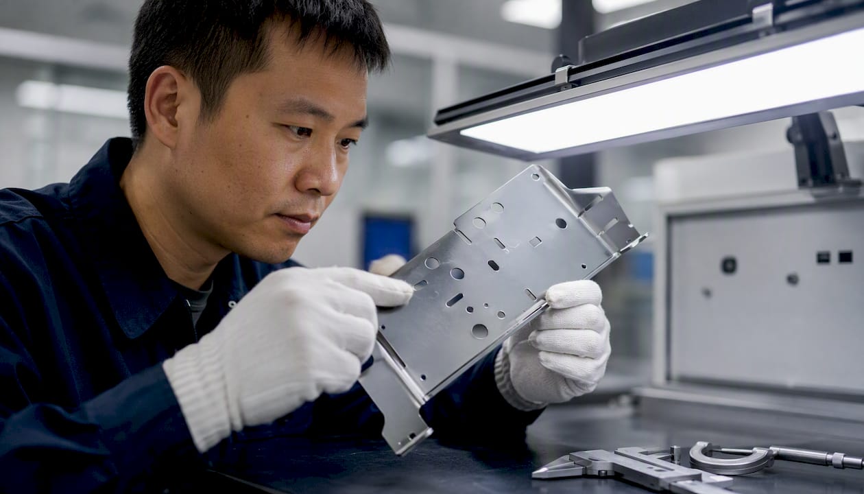
Holes placed too close to a bend line don’t stay round. The material pulls toward the bend during forming, distorting the hole and making it useless for fasteners or alignment. The fix is simple: respect the clearance rules.
Core placement rules (from Xometry’s fabrication design guide):
- Hole to bend line: ≥ 2T + R
- Slot to bend line: ≥ 4T + R
- Hole to part edge: ≥ 2T
- Hole-to-hole spacing (center to center): ≥ 6T for punched holes in thin material
- Minimum hole diameter: ≥ T (larger for high-strength alloys)
- Minimum slot width: ≥ T; slot length ≤ 5× slot width to avoid punch deflection
When a hole must sit closer to a bend than 2T+R allows, add a relief slot between the hole and the bend line. The slot interrupts the stress path and prevents distortion. This is a common fix on bracket flanges where hole patterns are constrained by mating geometry.
Slug capture is a punching-specific concern. Small slugs from punched holes can get pulled back up through the die and damage tooling or the part surface. Minimum hole diameter for punching is typically T, but some shops require 1.2T for stainless to prevent slug pull-back. Flag this in your DFM review if your part has many small holes in stainless or hardened material.
Pro Tip: If your design has slots oriented parallel to the bend line, they’re more likely to distort than slots perpendicular to it. Rotate slots 90° where geometry allows, and you’ll avoid a common source of first-article failures.
4. Stiffeners, Flanges, And Hems: When To Add Them And Minimum Dimensions
A flat sheet panel with no features will deflect under load and vibrate. Stiffeners and hems solve both problems, but they come with their own DFM constraints.
Flanges are the most common stiffening feature. The minimum flange height for standard press-brake air bending is approximately 3T. Below that, the tooling can’t grip the material reliably, and you’ll need special tooling or a different forming strategy. For a 2mm thick part, that means a minimum 6mm flange. Flanges shorter than 3T are one of the most common DFM violations caught in design reviews.
Hems fold the edge of a sheet back on itself, eliminating the sharp edge and adding local stiffness. Three types are common in production:
- Open hem: the return leg doesn’t contact the base material; inside diameter ≥ T. Used where some gap is acceptable and full closure isn’t needed.
- Closed hem: the return leg is pressed flat against the base. Requires a two-step forming operation (pre-bend, then close). Minimum return length ≈ 4T.
- Teardrop hem: a rounded loop hem used where a smooth, rounded edge profile is needed. More tooling-intensive than open or closed.
For most enclosure and bracket work, the open hem is the lowest-cost option. Closed hems add a forming step and require the inside surface to be clean, since any coating or burr on the inner face will cause the hem to spring open.
Stiffening ribs pressed into flat panels add rigidity without adding material. Keep rib depth ≤ 3T and rib width ≥ 3× rib depth to avoid tearing. Space ribs symmetrically to prevent warping during forming. When stiffeners are added, they change the forming sequence: the shop must form ribs before flanges in most cases, so flag this in your drawing notes.
Avoid tiny return flanges (under 3T) on parts that also have stiffening ribs. The combination of two forming features in close proximity often requires custom tooling, which adds cost and lead time.
5. Finishing And Assembly: Welds, Fasteners, Inserts, And Coatings
Design for assembly before the part reaches the shop floor. Features that look fine in CAD become expensive problems when a welder can’t reach a joint or a PEM insert is too close to a bend.
Welding considerations:
- Maintain weld access clearance: at least 1″ (25mm) of open space around any weld joint for a MIG gun; TIG requires more.
- Avoid designing welds at inside corners where two flanges meet at 90°. These are difficult to access and prone to incomplete fusion.
- Specify weld symbols on the drawing. “Weld all around” is not a substitute for a clear joint callout.
- For thin sheet (under 1.5mm), consider spot welding or laser welding instead of MIG to reduce distortion.
Fasteners and inserts:
- PEM inserts (threaded standoffs, nuts, studs) require a minimum edge distance of 2× the insert diameter from any edge or bend.
- Tapped holes in sheet metal are weak. For any fastener that will be assembled and disassembled more than once, use a PEM nut or insert.
- Countersunk holes for flush fasteners: countersink depth ≤ 0.6T to avoid breaking through the back face.
Surface finishing and coating:
- Powder coat adds 0.003″–0.005″ per surface. Account for this in hole diameters and clearance fits.
- Anodizing (aluminum) adds 0.0002″–0.001″ per surface; hard anodize adds more.
- Bead blast before powder coat improves adhesion but can close small holes or distort thin features. Flag critical holes on the drawing.
- Laser-cut edges often have a slight taper and oxide layer. Specify “deburr and break all edges 0.010” max” on the drawing if edge condition matters for assembly or safety.
Assembly checklist before release:
- Weld joint access confirmed for tool clearance
- Bend orientation allows part insertion into mating assembly
- Screw access holes are large enough for the driver (not just the fastener)
- PEM insert locations respect edge and bend clearances
- Critical edges called out for deburring on the print
Pro Tip: Specify “deburr all edges, 0.010” max break” as a general note on every drawing. Without it, shops make their own judgment calls, and what’s acceptable to one operator isn’t to another. One line on the print eliminates a recurring inspection argument.
6. Typical Shop Tolerances And The Cost Of Over-specifying Them
Most sheet metal parts don’t need tight tolerances. Calling out ±0.005″ on every dimension adds inspection time, increases scrap risk, and can double the cost of a simple bracket.
ISO 2768-m (medium) is the right general tolerance baseline for commercial sheet metal work. Apply it as a drawing note and only call out tighter tolerances where a specific functional requirement demands it.
Typical U.S. shop tolerances (from Xometry’s design guide):
| Dimension type | Typical shop tolerance | Notes |
|---|---|---|
| Linear (laser cut) | ±0.005″ | Achievable on most CNC laser tables |
| Bend-to-feature | ±0.010″ | Bend-to-hole location; affected by springback |
| Forming / bending | ±0.020″ | Cumulative across multiple bends |
| Angular | ±1° | Tighter requires iterative setup |
| Hole diameter (punched) | ±0.003″ | Depends on tooling condition |
Angular tolerances tighter than ±1° and bend-to-hole tolerances tighter than ±0.010″ are the two dimensions that most reliably drive up cost. They require iterative press-brake setup, first-piece CMM inspection, and often a dedicated fixture. Reserve them for genuinely functional features: a hinge pin hole, a precision locating slot, or a mating surface that must align with another precision component.
For aerospace or medical parts where tighter tolerances are unavoidable, the cost impact is real. Precision fabrication for aerospace involves additional inspection steps and process controls that standard commercial work doesn’t require. Budget accordingly and communicate requirements clearly in the drawing package.
First-piece inspection plus periodic sampling is the standard for most production runs.
7. Material Selection And Thickness: How Alloy Choice Changes Your DFM Rules
Material choice is a DFM decision, not just a structural one. The alloy you pick determines minimum bend radii, finishing options, and which features are even feasible.
| Material | Min bend radius | Corrosion resistance | Typical finish | Best for |
|---|---|---|---|---|
| Mild steel (CR) | 1T | Low (needs coating) | Powder coat, paint | Structural brackets, enclosures |
| Aluminum 5052-H32 | 1T | Good | Anodize, powder coat | Lightweight panels, marine |
| Aluminum 6061-T6 | 3T | Good | Anodize | Machined features, high-strength |
| Stainless 304 | 1.5–2T | Excellent | Passivate, bead blast | Food, medical, exposed hardware |
| Stainless 316 | 1.5–2T | Superior (chloride) | Passivate | Marine, chemical environments |
| Galvanized steel | 1T | Moderate | Paint, powder coat | Outdoor enclosures, HVAC |
For more on material tradeoffs in fabrication, advanced sheet metal materials covers alloy selection in depth.
Thickness ranges: standard sheet metal for press-brake work runs from 0.020″ (0.5mm) to 0.250″ (6.35mm). Above 0.250″, you’re typically in plate territory, and forming requires heavier equipment. Laser cutting handles thin sheet well; waterjet or plasma becomes more practical above 0.5″.
Grain direction and thickness verification: always verify incoming material thickness with a micrometer before designing to a nominal gauge.
Pro Tip: If your part needs both tight bend radii and good corrosion resistance, Al5052 is almost always the better choice over 6061-T6. The 3T minimum radius on 6061 forces larger flanges and tighter nesting constraints that add cost. Reserve 6061 for parts that need machined features or higher structural loads.
8. DFM Checklist And Common Failure Modes
Run this checklist in every design review before releasing a part for quoting. It takes 10–15 minutes and catches the issues that cause first-article failures.
DFM checklist:
- [ ] Uniform wall thickness throughout (no abrupt thickness changes)
- [ ] Inside bend radii meet material minimums (1T, 1.5–2T, or 3T per alloy)
- [ ] All holes ≥ 2T+R from bend lines; slots ≥ 4T+R
- [ ] Minimum hole diameter ≥ T
- [ ] Minimum flange height ≥ 3T
- [ ] Bend relief added at all bend terminations (width ≥ T, depth ≥ R+T)
- [ ] ISO 2768-m called out as general tolerance; tighter tolerances flagged with functional justification
- [ ] Deburr note on print (“deburr all edges, 0.010” max break”)
- [ ] Nesting orientation noted in DXF (grain direction)
- [ ] PEM insert locations respect 2× diameter edge clearance
- [ ] Weld access confirmed for all joints
- [ ] Finish spec includes thickness allowance for coating
Common failure modes and immediate fixes:
| Failure mode | Root cause | Fix |
|---|---|---|
| Cracking at bend | Radius too tight for alloy | Increase R; change to more ductile alloy |
| Hole distortion | Hole too close to bend | Move hole or add relief slot |
| Warping after forming | Asymmetric bend layout | Symmetric design; staged bending |
| Springback variation | Angular tolerance too tight | Loosen to ±1°; let shop compensate |
| Slug pull-back | Hole too small for punching | Increase diameter to ≥ 1.2T for stainless |
| Flange collapse | Flange < 3T | Increase flange height |
For a broader look at how these issues manifest in production, common quality issues in sheet metal fabrication covers real-world defect patterns and inspection strategies.
10–15 minute DFM review process:
- Open the STEP file and check wall thickness uniformity (use CAD measurement tool).
- Identify all bends and verify inside radius per material spec.
- Check every hole and slot against the 2T+R and 4T+R clearance rules.
- Confirm minimum flange heights on all flanges.
- Check for bend terminations at edges and add relief slots where missing.
- Review the drawing for tolerance callouts; remove any that aren’t functionally justified.
- Confirm finish spec and add deburr note if absent.
- Export DXF with grain direction marked; verify STEP is current.
9. Worked Example: Calculating Bend Allowance For A Two-bend Bracket
Result first: a simple L-bracket in 2mm mild steel with two 90° bends, inside radius 2mm, K-factor 0.38, produces a flat blank length of 114.8mm from two 50mm legs.
Setup:
- Material: mild steel CR, T = 2mm
- Inside bend radius: R = 2mm (= 1T, within the 1T minimum for mild steel)
- Bend angle: θ = 90°
- K-factor: K = 0.38 (air bending, mild steel)
- Leg A: 50mm; Leg B: 50mm; two bends
Step 1: Calculate bend allowance for one bend
BA = π × (R + K × T) × (θ / 180)
BA = π × (2 + 0.38 × 2) × (90 / 180)
BA = π × (2 + 0.76) × 0.5
BA = π × 2.76 × 0.5
BA = 3.14159 × 1.38
BA = 4.34mm per bend
Step 2: Calculate flat blank length
Flat length = Leg A + BA + Leg B + BA (for two bends)
Flat length = 50 + 4.34 + 50 + 4.34
Flat length = 108.68mm
Wait: the legs here are outside dimensions. If Leg A and Leg B are measured from the outside of the part, you need to subtract the material thickness and radius from each leg before adding BA. For inside-dimension legs (measured from the bend line):
Flat length = 50 + 4.34 + 50 + 4.34 = 108.68mm
For outside-dimension legs, subtract (R + T) from each leg first:
Adjusted Leg A = 50 − (2 + 2) = 46mm
Adjusted Leg B = 50 − (2 + 2) = 46mm
Flat length = 46 + 4.34 + 46 + 4.34 = 100.68mm
Step 3: Springback check
At 1T radius in mild steel, springback is typically 1–2°. The shop will program the press brake at approximately 88° to achieve a formed 90°. No design change needed; note this in your DFM review so the shop knows you’re aware and have not over-toleranced the angle.
Step 4: Validate
Confirm the flat blank fits within your available sheet size and nesting layout. If the shop uses a different K-factor (some shops run 0.33 for mild steel on their specific tooling), the flat length shifts by less than 1mm at this scale. Request the shop’s K-factor table if dimensional accuracy is critical, and run a first-article check before releasing the full production quantity.
For AI-assisted DFM checks that can automate K-factor lookups and flag clearance violations, AI tools for DFM covers the current software options worth evaluating.
What Production Actually Teaches You About Sheet Metal DFM
The rules in this guide are well-established, but the gap between knowing them and applying them consistently is where most design problems originate. The single most common issue in production runs isn’t a catastrophic design error. It’s a flange that’s 2.5T instead of 3T, or a hole that’s 1.8T+R from the bend instead of 2T+R. These are small deviations that look fine in CAD and cause first-article failures that delay programs by weeks.
Two habits separate engineers who ship clean parts from those who don’t. First, they engage the fabricator before the design is locked. A 30-minute pre-quote DFM review with the shop catches the features that are technically possible but expensive, and it surfaces tooling constraints that no design guide fully captures. Second, they keep bend directions consistent. Every time a part needs to be flipped or reoriented on the press brake, setup time increases and the chance of a sequencing error rises. Designing all bends in the same direction is a small constraint in CAD that pays real dividends on the shop floor.
Over-tolerancing is the other consistent cost driver. Engineers who come from machining backgrounds often apply machined-part tolerances to sheet metal drawings out of habit. A ±0.005″ callout on a bend-to-hole dimension that could function at ±0.020″ doesn’t make the part better. It makes it more expensive and slower to inspect. Default to ISO 2768-m, justify every tighter callout in writing, and you’ll find most of them disappear.
HLH SHEET METAL: From Dfm-compliant Design To Finished Parts
When your design is DFM-ready, the next step is a fabricator that can actually execute it. HLH SHEET METAL runs laser cutting, CNC press-brake bending, welding, stamping, and surface finishing across ISO-certified manufacturing facilities, handling everything from single prototypes to large production runs. Upload your STEP and DXF files and the team provides a DFM review alongside your quote, catching clearance violations and tolerance issues before the first plate is cut. English-speaking engineering support means you get direct answers, not translated summaries. Request a quote or DFM review and see the full fabrication capabilities to match your design to the right process.
Sources
- Design Guide: Sheet Metal Fabrication VERSION 2.2
- Sheet metal DFM – design guidelines for formed and punched parts
- DFMPro for Sheet Metal Design Guidelines
- Minimum inside sheet metal bend radius vs what’s recommended
FAQ
What Is Sheet Metal DFM?
Sheet metal DFM (design for manufacturability) is the practice of designing parts so they can be fabricated efficiently, accurately, and at low cost using standard sheet metal processes. It covers bend radii, hole placement, tolerances, material selection, and feature sizing.
What Is A DFM Checklist For Sheet Metal?
A sheet metal DFM checklist verifies uniform thickness, minimum bend radii by alloy (1T for mild steel, 3T for 6061-T6), hole-to-bend clearances (≥ 2T+R), minimum flange height (≥ 3T), bend relief at edge terminations, and ISO 2768-m as the general tolerance standard.
What Are DFM Guidelines For Sheet Metal Fabrication?
DFM guidelines for sheet metal specify minimum inside bend radii, hole and slot clearances from bends and edges, minimum flange and hem dimensions, and tolerance standards. The core rules are material-dependent: Al6061-T6 requires a 3T minimum radius while mild steel and Al5052 can form to 1T.
What Is The Difference Between DFM, DFA, And DFMEA?
DFM (design for manufacturability) focuses on making parts easy to fabricate. DFA (design for assembly) focuses on making parts easy to assemble. DFMEA (design failure mode and effects analysis) is a structured risk analysis that identifies how design choices could cause failures in manufacturing or in service.
When Should I Involve A Fabricator In The DFM Process?
Involve the fabricator before the design is locked, ideally at the pre-quote stage. A DFM review at that point catches impossible or expensive features before any material is cut, which is consistently the lowest-cost point to make design changes.

