



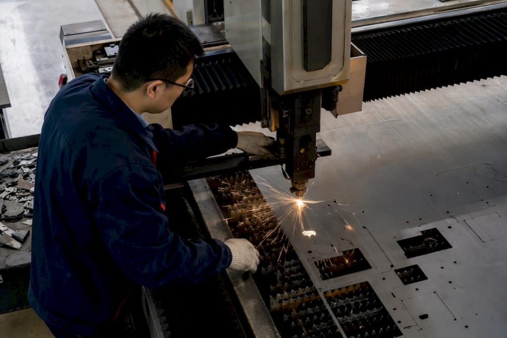

Table Of Contents
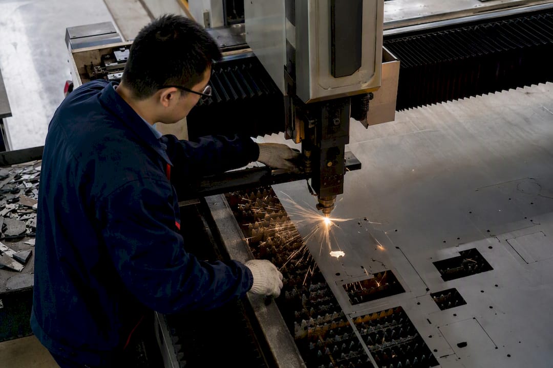
Set flat-part tolerances at ±0.005″ (±0.127 mm), hole and slot tolerances at ±0.005″ to ±0.010″, and over-bend dimensions at ±0.030″ as your default. Tighten tolerances only on features that control fit, sealing, or press-fit assembly, and say so explicitly on the drawing. That single distinction, “controlled feature” versus “general dimension,” is what separates a quote that comes back clean from one that comes back with a dozen clarifying emails.
Laser cutting tolerances hinge on three physical realities: kerf width, thermal taper, and machine repeatability. A fiber laser can hold near-zero taper on thin-to-medium gauge steel and aluminum, but that capability only shows up in your parts if your drawing tells the supplier which dimensions actually matter.
Three things belong on every drawing headed to a fabricator, in China or anywhere else:
- Material spec and thickness tolerance, called out by alloy and gauge, not just “steel.”
- Feature-critical tolerances tied to an inspection method, CMM for positional and hole-diameter checks, optical comparator for edge profile and small features.
- A first-article inspection (FAI) requirement on the initial run, with a report you actually review before production starts.
Pro Tip: Reference ISO 59752 or the relevant ASTM material standard directly on the drawing. It turns a vague tolerance request into a contractual acceptance criterion your supplier can’t argue with later.
Precision here is not academic. HLH SHEET METAL builds server rack enclosures and structural brackets where a 0.1 mm miss on a mounting hole means a re-tap, a stripped thread, or a returned assembly.
Key Takeaways
Laser-cut precision comes from matching tolerance tightness to functional need, verifying supplier machine capability, and confirming inspection methods before production starts.
| Point | Details |
|---|---|
| Default to standard bands | Use ±0.127 mm on flat cuts and ±0.010″ on single bends unless a feature controls fit. |
| Reserve tight tolerance for critical features | Apply ±0.05 mm only where assembly, sealing, or press-fit performance demands it. |
| Follow the 1T minimum rule | Keep hole and slot diameters at or above material thickness to avoid poor roundness. |
| Verify supplier machine capability | Ask about closed-loop compensation, CMM reports, and ISO certification before ordering. |
| Work with HLH SHEET METAL for verified runs | HLH SHEET METAL offers ISO-certified QA, CMM inspection, and FAI documentation across its China plants. |
Why Precision DFM For Sheet Metal Depends On Tolerance Discipline
Every laser-cut dimension carries two kinds of error: dimensional (is the hole the right diameter?) and positional (is it in the right place relative to everything else?). Kerf, the material the beam actually vaporizes, shifts both. A 0.2 mm kerf on a 3 mm mild steel sheet doesn’t just widen a hole; it shifts every downstream measurement if your CAM software isn’t compensating for it consistently across the nest.
That compounding matters most at assembly. A bracket that’s 0.1 mm off on a single hole is a nuisance. A bracket that’s 0.1 mm off on four holes that all need to align with a mating panel is a part that gets rejected on the floor. Sealing faces and gasket surfaces are even less forgiving, since taper on a cut edge translates directly into an uneven mating surface.
Before you commit to a supplier, ask for three numbers. First, their repeatability spec in real ± values, not marketing language like “high precision.” Second, what inspection method backs that number, CMM data holds more weight than a caliper check on a sample part. Third, whether their quality system is ISO-certified, because that certification implies documented process control, not just a good machine on a good day.
Kerf, Taper, And Cut-edge Geometry: What To Expect
Kerf is the width of material removed by the laser beam. Taper is the angular deviation of the cut wall from perfectly vertical. Both vary by material, thickness, and laser type, and both are predictable enough to design around once you know your supplier’s numbers.
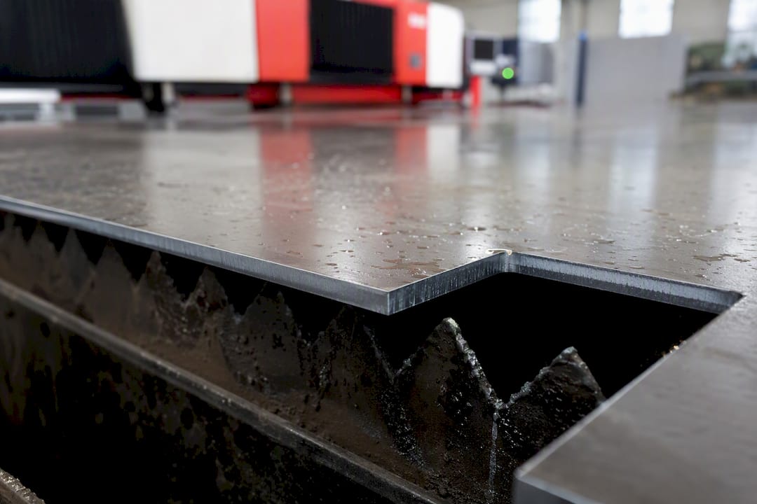
Kerf width typically runs narrower on fiber lasers than on older CO2 systems, especially on reflective metals like aluminum and copper, where fiber’s shorter wavelength couples into the material more efficiently. On mild steel between 1 and 6 mm, expect kerf in the range of 0.1 to 0.3 mm; thinner stock cuts narrower, thicker stock wider. Taper stays close to zero on thin gauges but becomes noticeable past 6 mm, where the beam has more material depth to travel through and the top and bottom edges of the cut diverge slightly.
Compensate in CAD by offsetting your cutting path from the nominal profile, inward for holes, outward for outer contours, by half the kerf width. Most CAM software handles this automatically once you specify kerf value, but confirm your supplier’s default rather than assuming it matches your model.
Taper matters most on press-fit holes, dowel locations, and any feature that mates with a shaft or pin. On those features, request top-and-bottom profile measurements, not just a single diameter reading, so you can see whether the hole is genuinely cylindrical or slightly conical.
Pro Tip: Ask your supplier for a CMM report showing both top and bottom hole diameters on a sample part. If the two numbers diverge by more than 0.02 to 0.03 mm on a thin sheet, that’s a sign of poor focal control, not just normal taper.
A useful reference diagram would show the cut cross-section: entry point at the top surface, the kerf width labeled at both surfaces, and the taper angle marked as the deviation between top and bottom edge lines.
Minimum Hole, Slot, And Small-feature Rules
The baseline rule engineers should memorize: minimum hole or slot diameter equals material thickness, expressed as 1T. Cut a hole smaller than your sheet is thick and you risk poor roundness, excess dross, or the laser simply failing to pierce cleanly. On high-strength alloys or highly reflective metals like polished aluminum, bump that minimum up, since those materials resist clean small-feature cutting even when a mild steel equivalent would cut fine.
Edge distance rules follow similar logic. Keep holes at least 2×MT from any outer edge, and if a hole sits near a bend line, push that clearance to 6×MT to avoid distortion during forming. Slots need proportionally more clearance than round holes because their geometry concentrates thermal stress unevenly along the length of the cut.
Feature clustering degrades quality as thickness increases. On thick stock, tightly packed small holes trap heat between features, warping the sheet locally even when each hole individually falls within spec. If your design needs a dense hole pattern on thick material, consider relief cuts between clusters or moving the smallest features to a secondary machining step instead of forcing everything through the laser.
These figures follow the 1T minimum-diameter and 2×MT edge-distance rules that most sheet-metal DFM guides converge on. Treat them as a floor, not a target, when you’re designing for repeatable production rather than a one-off prototype.
Standard Laser-cut Tolerance Bands And How To Allocate Them
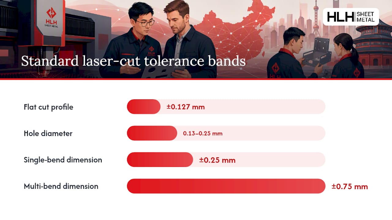
Not every dimension on a drawing deserves the same tolerance, and treating them all the same is how quotes balloon. Flat, single-plane laser-cut features commonly hold ±0.005″ (±0.127 mm) without any special process controls. Hole diameters typically run ±0.005″ to ±0.010″ depending on hole size and material. Once a part gets bent, tolerances loosen: a single-bend dimension is commonly held to ±0.010″, while a dimension spanning multiple bends and surfaces often relaxes to ±0.030″ because each bend introduces its own springback variation.
The allocation strategy that actually works: pick one datum scheme per part, usually two edges and a hole, and tolerance every other feature relative to that datum rather than chaining tolerances from feature to feature. Chained tolerances stack, and a part with six ±0.005″ dimensions in series can end up with 0.03″ of accumulated error at the far end, even though each individual call-out looks tight.
Use GD&T instead of decimal tolerances when a feature’s location matters more than its exact coordinate, hole patterns that mate with another part are the clearest case. Decimal tolerances are fine, and cheaper to inspect, for overall envelope dimensions that don’t interact with anything else.
| Feature type | Typical tolerance | When to tighten |
|---|---|---|
| Flat cut profile | ±0.127 mm (±0.005″) | Mating edges, sealing surfaces |
| Hole diameter | ±0.13 to ±0.25 mm | Press-fit, dowel locations |
| Single-bend dimension | ±0.25 mm (±0.010″) | Rarely needed tighter |
| Multi-bend dimension | ±0.75 mm (±0.030″) | Add secondary fixture if tighter needed |
Pro Tip: Every tolerance you tighten below the standard band adds inspection time and, often, a secondary fixturing step. Reserve very tight tolerances for the few dimensions on the part that genuinely control fit, and apply standard tolerance bands to other features.
How Material And Thickness Change Achievable Tolerance
Thermal conductivity and reflectivity drive most of the variation you’ll see between materials. Aluminum conducts heat away from the cut zone quickly, which narrows the heat-affected zone (HAZ) but also demands higher laser power and tighter focal control to maintain clean edges. Copper and brass reflect enough of a fiber laser’s wavelength that they need specific machine settings and, in copper’s case, sometimes a different assist gas strategy entirely to cut reliably.
Stainless steel typically runs with nitrogen assist gas to prevent oxidation at the cut edge, producing a bright, weld-ready finish. Mild steel usually runs with oxygen assist, which cuts faster and cheaper but leaves an oxide layer that can affect downstream coating or welding. Galvanized and galvanneal steels sit in between, coatings can vaporize unevenly at the cut edge, which is worth flagging if your part needs a clean edge for plating.
Laser cutting stays the right process choice up to roughly 1/4″ (6 mm) for most steels and aluminum alloys. Past that, plasma or waterjet typically produce better economics and comparable or better edge quality on flat parts, since laser cut speed and edge quality both degrade on very thick stock.
- Reflective metals (aluminum, copper, brass) often need specific machine tuning, not just a power adjustment.
- Stainless steel with nitrogen assist costs more per cut but avoids oxide scale.
- Galvanized coatings can burn back from the cut edge, affecting plating adhesion nearby.
Pro Tip: Ask which assist gas your supplier defaults to for your material. A shop running oxygen assist on stainless steel to save cost will hand you a part with an oxide edge you didn’t ask for.
Feature Spacing, Web Widths, And Nesting For Dimensional Stability
Spacing rules exist because heat from one cut affects the material around the next one. Hole-to-hole spacing should generally sit at 2×MT minimum, and closer to 6×MT if either hole sits near a bend line where distortion risk compounds. Slot-to-slot spacing needs more room than round holes because slots concentrate stress unevenly along their length.
Minimum web width, the strip of material left between two cut features, follows the same logic: too narrow, and the web can tear or bulge during the cut itself, before the part ever reaches a press brake. Add relief cuts wherever a web width drops below your material thickness, and make the relief longer than the theoretical minimum whenever the feature sits near a bend.
Nesting decisions differ meaningfully between prototype and volume runs. A prototype nest optimizes for turnaround, packing parts tightly with less regard for heat buildup across the sheet. A production nest should leave more thermal breathing room between parts, because cumulative heat across a densely packed sheet causes parts near the center to warp slightly more than parts near the edge, an effect that’s invisible on a single prototype but shows up as inconsistent batch quality at volume.
- Hole-to-hole spacing: 2×MT minimum, 6×MT near bends.
- Web width: never less than 1×MT; add relief cuts below that threshold.
- Production nests need more thermal spacing than prototype nests, even at the cost of material yield.
Pro Tip: If your supplier quotes a tighter nest for volume production than they used on your prototype, ask why. Tighter nesting at volume usually means they’re optimizing for material cost, not dimensional consistency.
Designing Laser-cut Geometry For Bending And Forming
A laser-cut flat pattern is only half the part. Bend allowance and neutral axis shift determine whether your flat geometry actually forms into the dimensions on your 3D model, and getting this wrong is one of the most common reasons a “correctly cut” part fails at assembly.
Keep bend radius at or above 1×material thickness as a baseline. Tighter radii risk cracking on the outside of the bend, especially on harder alloys or material that’s been work-hardened from a prior operation. Uniform material thickness through the bend zone matters just as much: any laser-cut feature, hole, notch, or slot, sitting right at a bend line becomes a stress concentrator and a likely crack initiation point.
Move features off the bend line by at least 2 to 3 times material thickness, more for critical structural parts. If a feature genuinely needs to sit near a bend, add a relief cut, at least 1×MT wide and longer than the bend radius, to give the material somewhere to deform without tearing.
- Bend radius: minimum 1×MT, more for harder alloys.
- Keep holes and slots 2 to 3×MT away from bend lines.
- Relief cuts: minimum 1×MT wide, longer than the bend radius itself.
A useful CAD-to-flat illustration would show the flat pattern with the bend line marked, the neutral axis position labeled, and a relief cut called out at the point where a slot approaches the bend, demonstrating the minimum clearance visually rather than just in a table.
Deburring, Edge Quality, And Secondary Operations
As-cut laser edges are usable for most non-mating surfaces, but decide edge condition deliberately rather than by default. Mechanical deburring removes dross and sharp edges cheaply. Tumbling and bead blasting improve consistency across a full batch. Grinding and passivation, especially on stainless steel, address both edge sharpness and corrosion resistance for parts headed into regulated industries.
Call out edge condition explicitly whenever it matters, “deburred, no sharp edges” or a specific Ra surface finish value, since secondary ops shift inspection criteria and add cost.
- Mechanical deburr: removes dross, minimal dimensional impact.
- Tumbling/bead blast: consistent finish across a batch, slight edge rounding.
- Grinding/passivation: needed for corrosion resistance or cosmetic edges.
Pro Tip: Countersinks and counterbores almost always require a secondary machining step, not a laser feature. Flag them explicitly, because a supplier quoting “laser cut only” will not include that operation by default.
Verifying Supplier Capability For Micron-level Tolerances
Getting a supplier to commit to a tolerance on paper is one thing. Getting them to actually hold it across a production run depends on machine technology and process control you should verify before placing an order, not after parts arrive out of spec.
Ask specifically about closed-loop CNC compensation, sometimes called LAMS (Laser Alignment Measurement System) or similar, which corrects for machine drift in real time rather than relying on periodic recalibration. Ask what their typical repeatability is in real ± numbers, and what inspection equipment backs that claim: CMM for positional accuracy, optical comparators for edge profile and small-feature verification.
Traceability matters as much as the raw numbers. ISO certification implies documented process control and audit trails, not just competent machine operators. First-article inspection (FAI) and defined sampling plans give you a checkpoint before committing to a full production run, and reviewing common QC failure points in Chinese sheet-metal sourcing before you finalize an RFQ tends to surface issues earlier than waiting for the first shipment.
- Ask for machine type: fiber laser vs. CO2, and whether it has closed-loop compensation.
- Request recent CMM capability data, not a marketing spec sheet.
- Confirm ISO certification and a documented FAI/sampling process.
Pro Tip: Request a CMM report from a recent, unrelated production run, not a cherry-picked sample part. It tells you what the machine actually holds under normal conditions, not its best-case performance.
HLH Sheet Metal’s Capability Snapshot For Precision Tolerances
HLH SHEET METAL runs custom fabrication across laser cutting, bending, welding, and finishing for clients spanning aerospace, medical, and industrial sectors, with multiple manufacturing plants in China supporting both prototype runs and volume production.
Rapid prototyping runs alongside ISO-certified quality assurance protocols, which means a design change between prototype and production doesn’t require restarting your qualification process from scratch. If you need documentation before committing to an order, request a precision QC review covering inspection methods, sampling plans, and FAI reporting for your specific part geometry.
- Request a capability statement specifying achievable tolerance by material and thickness.
- Ask for FAI documentation on the first production batch before authorizing full-run shipment.
- Confirm English-fluent support for technical back-and-forth on drawing clarifications.
Practical DFM Checklist And Example Drawing Notes
Copy this checklist onto your next RFQ or drawing package before it leaves your desk:
- Material spec and alloy, with thickness tolerance called out explicitly.
- Minimum hole/slot diameter confirmed against the 1T rule for your chosen material.
- Datum scheme defined: two edges plus one hole is the common baseline.
- Surface finish or edge condition specified for any cosmetic or mating surface.
- Inspection method stated per critical dimension (CMM, optical, or caliper-acceptable).
- FAI sign-off required before production release, with a defined sample size.
| Tolerance class | Achievable tolerance | Minimum hole | Edge quality | Cost impact |
|---|---|---|---|---|
| Typical | ±0.13 mm | 1×MT | As-cut, minor dross | Baseline |
| Tight | ±0.005″ to ±0.010″ | 1×MT, tighter roundness | Deburred | Moderate increase |
| Micro-precision | ±0.05 mm | 1×MT with closed-loop compensation | Ground or passivated | Highest, CMM 100% |
Two drawing notes worth adapting directly: “All hole locations ±0.05 mm unless otherwise noted; CMM inspection report required on first 5 pieces.” And for general dimensions: “Unless otherwise specified, flat profile tolerance ±0.13 mm per ASTM reference standard; bent dimensions per single-bend tolerance table.”
How To Specify Tolerances And Gd&t On Drawings
Decimal tolerances work fine for envelope dimensions and non-mating features. Switch to GD&T when a feature’s position relative to another feature matters more than its absolute coordinate, hole patterns for fasteners or press-fit locations are the clearest example.
A basic GD&T callout for hole position might read: position tolerance 0.1 mm at maximum material condition (MMC), referenced to datums A, B, and C. For perpendicularity on cut edges near mating surfaces, a rule of thumb is to allow 0.05 to 0.1 mm of taper deviation per millimeter of material thickness, tighter if the surface seals against a gasket.
State your inspection method as part of the acceptance criteria itself: “CMM 100% inspection on positional features” reads very differently to a supplier than “sample-based FAI, first 5 pieces only.” Both are legitimate approaches, but only one belongs on a part where every unit needs to fit.
A Note On Prioritizing Precision Versus Cost
Tighter tolerances cost more in inspection time and rejected parts, so spend that budget only where it changes fit or function. Decide prototype tolerances loosely and tighten specific features for volume production once you know which dimensions actually drive assembly problems. Sheet-metal fabrication rewards engineers who negotiate capability with their supplier directly rather than guessing.
Getting A Tolerance-verified Quote From HLH Sheet Metal
If you’ve mapped out your critical dimensions and you’re ready to move from design review to an actual quote, HLH SHEET METAL gives you a faster path than negotiating tolerance capability blind with an unfamiliar overseas shop. Send STEP files for 3D geometry and DXF for flat patterns, flag your critical dimensions explicitly (don’t rely on a supplier to guess which ±0.05 mm callouts actually matter), and request an FAI report or sample run before committing to full production.
HLH SHEET METAL runs ISO-certified quality assurance with CMM inspection available across its China manufacturing plants, backed by an English-fluent support team that can walk through drawing clarifications without the usual translation lag. Visit the precision sheet metal fabrication page to request a tolerance capability statement or start a quote on your next part.
Sources
Use the ISO standard listing and ASTM material standards when tolerance requirements need to become contractual acceptance criteria rather than informal requests. For broader DFM reading, HLH SHEET METAL’s fabrication guides and articles cover related topics like aerospace QA standards and manufacturing design fundamentals in more depth.
FAQ
What Are The Standard Tolerances For Sheet Metal Laser Cutting?
Flat laser-cut profiles commonly hold ±0.005″ (±0.127 mm), while hole diameters typically run ±0.005″ to ±0.010″ depending on size and material.
What Tolerance Should I Use For Laser Cutting Critical Features?
Reserve ±0.05 mm for features that control fit or sealing, since some fiber-laser setups can hold that tolerance with closed-loop compensation and proper inspection, but it adds inspection cost if applied everywhere.
What Are The DFM Guidelines For Sheet Metal Fabrication?
Key rules include keeping minimum hole diameter at 1× material thickness, maintaining bend radius at 1×MT minimum, and keeping features at least 2 to 6×MT from bends and edges depending on proximity.
How Do I Verify A Chinese Supplier’s Tolerance Capability?
Request recent CMM inspection reports, confirm ISO certification, and ask specifically about closed-loop machine compensation before committing to production; HLH SHEET METAL provides capability statements and FAI documentation for this exact purpose.
What Are The Standard Tolerances For Sheet Metal After Bending?
Single-bend dimensions typically hold ±0.010″ (±0.25 mm), while dimensions spanning multiple bends often relax to ±0.030″ (±0.75 mm) because each bend introduces its own springback variation.

