





Table Of Contents

For bolt holes in structural connections, keep the center-to-edge distance at 1.5 times the bolt diameter as an absolute floor, with 2 times the diameter recommended for full bearing capacity. For sheet metal, hole edges need to sit 1.5 to 2 times the material thickness from the part edge, with the higher multiple for punched parts and bends. Confirm final numbers against AISC Table J3.4 or the Aluminum Design Manual before locking a drawing.
TL;DR:
- Keep bolt hole center-to-edge distances at a minimum of 1.5 times the bolt diameter, with 2D recommended for maximum bearing strength and fatigue resistance.
- For sheet metal, ensure holes sit at least 1.5 times the material thickness from the edge, and 2T from bends to prevent tearing or warping.
- Punched holes typically require a minimum web width of 2T, while laser-cut parts can often go closer at 1.5T, with allowances for material and process differences.
- When holes are large or near corners, verify the ligament (remaining web) is sufficient, rather than relying solely on center-to-edge measurements.
- Always confirm minimum edge distances with applicable standards like AISC, Aluminum Design Manual, or your fabricator’s shop standards, especially for high-stress or cyclic loading conditions.
What Are The Standard Hole To Edge Distance Rules?
The numbers below cover the two situations that come up constantly: fastener holes in structural or mechanical assemblies, and holes cut into sheet metal parts during fabrication. They are not interchangeable, and mixing them up is a common source of rejected drawings.
For bolted connections, edge distance is measured from the hole’s center to the nearest edge, expressed as a multiple of the bolt diameter (D). The 1.5D to 2D rule shows up across steel and aluminum codes alike, with 1.5D typically the legal minimum and 2D the number engineers reach for when bearing strength and long-term fatigue performance matter. Tapped holes need extra caution: because thread engagement reduces the effective material around the hole, many shops push the practical minimum up toward 1.5D even where a through-hole might get by at 1.25D.
Sheet metal follows a different logic entirely, scaled to thickness (T) instead of fastener size. Hole-to-edge minimums run 1.5T to 2T, and hole-to-bend distances need 2T to 3T to avoid tearing or warping near the fold line.
| Feature | Common minimum | Recommended default |
|---|---|---|
| Bolt hole (structural) | 1.5D | 2D |
| Tapped hole | 1.25D to 1.5D | 1.5D |
| Sheet metal hole to edge | 1.5T | 2T |
| Hole to bend line | 2T | 2.5T to 3T |
Two of these rules deserve a second look before you trust them blindly:
- Center-to-edge multiples work fine for small holes, but as hole diameter grows relative to part size, check the remaining ligament (the actual material left between the hole wall and the edge) rather than just the center distance.
- A center-to-edge check can look compliant while the ligament underneath it is dangerously thin, especially on large-bore holes near a corner.
When in doubt, or when the part will see cyclic loading, default to the 2D or 2T column. It costs you a little material and saves you a redesign.
Which Standards Govern Edge Distance Requirements?
Code minimums are not suggestions, and they are not identical across materials. Each standard defines edge distance slightly differently, and the gaps matter when you are stamping approval on a drawing.
- AISC Table J3.4 sets minimum center-to-edge distances for steel bolts in structural connections, with Table J3.5 adding required increments for oversized or slotted holes.
- Aluminum Design Manual, Section J.5.3 treats aluminum fasteners separately, generally landing near 1.5D minimum with 2D flagged as preferable wherever bearing strength is a concern.
- Eurocode 3 and BS 5950 use comparable ratios but apply different partial safety factors, so a European steel connection can land on a slightly different number than an AISC-governed one for the same load case.
- RCSC specifications cover slip-critical bolted joints and layer additional requirements on top of the base AISC edge distance.
Treat every one of these as a starting point, not a finish line. The engineer of record has to sign off before any project departs from code minimums, no matter how solid the shop’s own DFM rules are.
How Does The Manufacturing Process Change Minimum Edge Distance?
The same hole-to-edge number can be safe on a laser-cut part and marginal on a punched one, because the two processes create completely different stress patterns around the hole.
Punching drives a die through the material, and that mechanical shear displaces metal outward from the hole, weakening the surrounding web. Shops typically hold punched parts to a 2T minimum, and punching’s shear and ovalization effects are exactly why that number sits higher than laser work. When a layout forces a tighter web than 2T allows, tooling changes such as a nibbling sequence or a redesigned punch profile can sometimes recover margin without moving the hole.
Laser cutting removes material with heat instead of force, so it leaves less residual stress at the edge. Mild steel parts often get away with 1.5T. Stainless steel and hard alloys don’t get the same break: heat affected zones and higher hardness push the safe minimum back toward 2T even on a laser table.
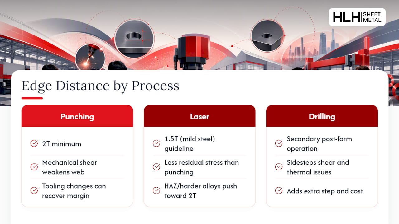
Drilling as a secondary, post-form operation is the fallback when layout truly won’t allow the primary process to hit target spacing. It costs an extra step but sidesteps both punching’s mechanical stress and laser’s thermal concerns.
Pro Tip: If your CAM software or nesting review flags a hole inside the 1.5 to 2T range, that flag exists for a reason. Treat it as a signal to either move the hole or open a conversation with your fabricator about a process change, not as a warning to override.
Why Do Holes Need Extra Distance From Bend Lines?
Bending stretches the metal at the outside of the fold and compresses it on the inside, and a hole sitting too close to that tangent line gets caught in the distortion. Keep hole edges at least 2T from the bend tangent, and use 2.5T plus the inside bend radius when the design allows it, especially on tighter radii or harder alloys.
When a hole lands too close to a fold, you have a handful of practical fixes:
- Relocate the hole further from the tangent line if the assembly tolerates it.
- Laser cut undersized, form the part, then ream or drill the hole to final size after bending.
- Add a relief slot or notch at the bend to absorb the stretch without distorting the hole.
- Extend the flange dimension so the hole naturally clears the 2T zone.
A thin aluminum flange with a mounting hole placed 1T from a 90 degree brake line is a textbook failure case. The hole typically ovalizes and the flange edge near it can crack or wave slightly, and once that part comes off the brake, there’s no fixing it without scrapping the run and moving the hole on the next iteration.
Bend behavior is also a minimum bend radius question as much as a hole placement one, since both interact at the tangent line.
How Do You Correctly Measure Hole To Edge Distance?
Two measurements get used, and mixing them up is where a lot of drawing reviews go wrong. Center-to-edge distance runs from the hole’s centerline to the nearest part edge. Edge ligament, sometimes called remaining web, is the actual material left once the hole diameter is subtracted: ligament = center-to-edge distance minus half the hole diameter.
- Calculate both numbers separately rather than assuming center-to-edge compliance guarantees an adequate ligament, particularly on holes larger than about a quarter of the part width.
- Add explicit minimum web callouts on the drawing, such as “minimum web 2×T at LMC” (least material condition), so tolerance stacking never quietly eats the margin.
- Specify the tolerance for hole distance the same way you would any other critical dimension, not as an afterthought buried in a general note.
- Verify with a caliper or optical comparator during first-article inspection, and flag any part measuring inside the design minimum before it reaches production volume.
Skipping the ligament calculation is one of the most common ways an edge distance check passes on paper and fails on the shop floor.
What Should Go On A Design Checklist For Edge Distance?
A short checklist catches most edge distance problems before they reach the shop floor:
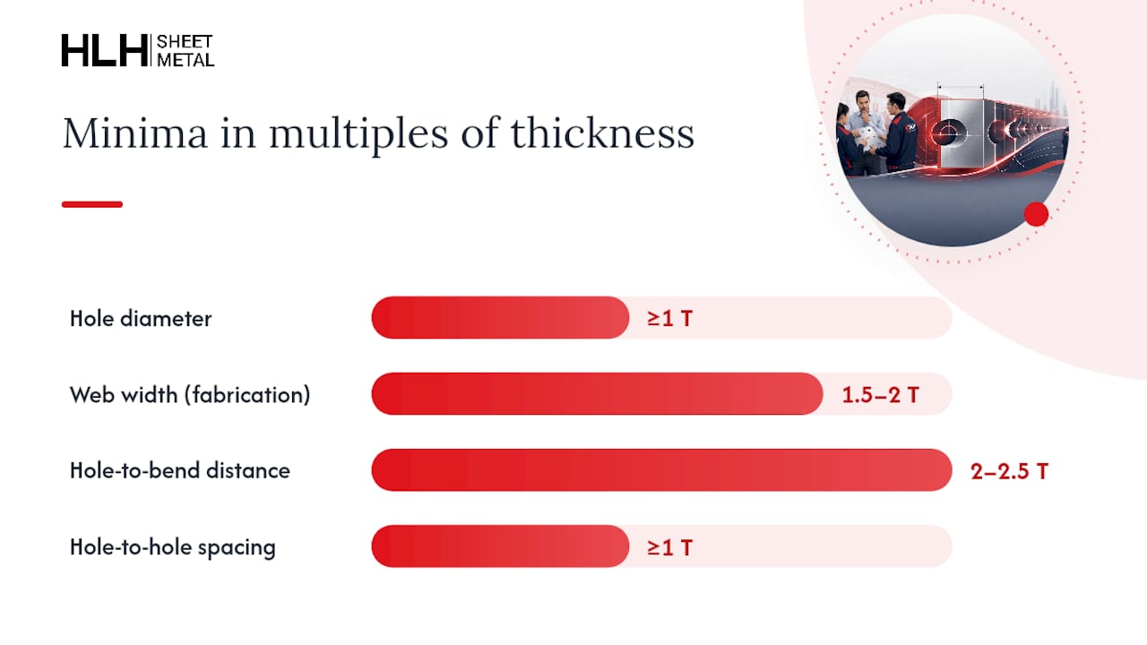
- Hole diameter should be at least equal to material thickness (hole Ø ≥ T) wherever possible.
- Web width needs to meet 1.5 to 2T depending on process, with punching held to the higher end.
- Hole-to-bend distance stays at 2 to 2.5T minimum from the tangent line.
- Hole-to-hole spacing holds at least 1T between adjacent features.
- Material and finish notes (plating thickness, alloy hardness) get called out where they affect the margin.
- Any exception below these defaults gets a documented engineer-of-record signoff before release.
Pro Tip: Keep a one-page version of this checklist next to your CAD station. Most edge distance violations happen during quick layout changes late in a project, not during initial design.
Two quick examples show how this plays out. A laser-cut aluminum enclosure panel with mounting holes near its perimeter can typically run at the 1.5T minimum on mild aluminum, provided first-article inspection confirms the actual web width matches the model. A punched steel bracket destined for a vibration-heavy application is a different story: push that one to 2T or beyond, and consider widening the flange rather than shaving the margin to save material. Reviewing sheet metal DFM practices before committing to a layout usually catches both of these cases early.
When Should You Use Larger Edge Margins Than The Minimum?
Code minimums assume ideal conditions. Real parts rarely offer those, and several factors push the smart number well above 1.5D or 1.5T.
- Fatigue loading, vibration, or repeated assembly and disassembly all argue for the 2D or 2T end of the range rather than the bare minimum.
- Plated or coated parts lose a small amount of effective material thickness, which erodes margin that looked adequate on the bare metal drawing.
- Thin gauges below roughly 0.06 inches leave little room for tooling variance, so shops often add margin there by default.
- Stainless steel and other high-strength alloys resist forming differently than mild steel, and holes near bends on these materials need the wider spacing discussed earlier.
The safe default is still 2D or 2T. Anything smaller belongs in a documented exception with engineer-of-record signoff and a corresponding note in the shop’s inspection plan, not a silent judgment call on the floor.
A Fabricator’s View On Edge Distance Defaults
Most edge distance failures in incoming designs aren’t code violations. They’re shop-reality gaps: a drawing that technically clears 1.5T but ignores what punching does to that specific alloy, or a hole placed exactly at the calculated minimum with zero allowance for tolerance stacking.
Some shops run slightly more conservative defaults than the bare code minimums for a reason: 2T for punched parts, 1.5T acceptable for laser-cut mild steel, and any hole under one material thickness in diameter may be rejected or flagged for a post-drilling operation. First-article checks measure the actual web width, confirm hole diameter against the model, and inspect bend-adjacent holes for distortion before a production run proceeds. If a design comes in marginal, the standard move can be a documented process swap rather than a silent pass.
The practical lesson for anyone submitting an RFQ: put the intended process, inspection level, and any post-form operations directly on the drawing or quote request. A hole spec that reads fine as a number means something different on a punch press than it does on a laser table, and that context is exactly what a fabricator’s manufacturing capabilities need to see before a firm quote goes out.
— Nash
Where To Verify These Numbers Yourself
For structural bolt tables, check the AISC Steel Construction Manual directly rather than a secondary summary. For sheet metal production rules, cross-reference hole and slot placement guidance against your specific fabricator’s shop standards, since defaults vary by shop and process.
Need a project quoted against these standards? HLH SHEET METAL’s sheet metal fabrication services run first-article checks on every marginal hole placement before production starts, and the team will flag any edge distance that needs a process change before it becomes a scrapped run. For layout math on fastener patterns, a tool like Bolt Circle Calc is worth bookmarking alongside your standards references.
FAQ
How Far Should Holes Be From The Edge?
For bolt holes, keep the center-to-edge distance at least 1.5 times the bolt diameter, with 2 times the diameter preferred for full bearing strength. For sheet metal, hold hole edges 1.5 to 2 times the material thickness from the part edge, with the higher figure for punched parts.
What Is The Formula For Edge Distance?
For fasteners, edge distance equals a multiple of bolt diameter (typically 1.5D to 2D). For sheet metal ligament checks, use ligament = center-to-edge distance minus half the hole diameter, and compare that ligament against the 1.5 to 2T minimum for your process.
What Is The Minimum Hole To Edge Distance For Sheet Metal?
The practical minimum is 1.5 times material thickness for laser-cut mild steel, rising to 2 times thickness for punched parts or harder alloys like stainless steel.
What Is The Recommended Edge Distance For A Tapped Hole?
Tapped holes generally need 1.5 times the bolt diameter as a working minimum, slightly more conservative than a comparable through-hole, because thread engagement reduces the effective material around the hole.

