




Table Of Contents
For most single-coat decorative and architectural work, aim for 60 to 80 µm (2.4 to 3.1 mils) of cured film. That window balances corrosion protection, appearance, and mechanical cure without wasting powder or risking cracking; to learn more about selection for exterior durability, see our top exterior coatings for commercial buildings. Harsher outdoor exposure or heavy-duty industrial parts push the target higher, sometimes into a two-coat system, but the core rule holds everywhere: staying inside the specified range matters more than hitting any single number.
TL;DR:
- Applying powder coatings within 60 to 80 µm (2.4 to 3.1 mils) is ideal for decorative and architectural purposes, balancing appearance and corrosion resistance.
- For outdoor or harsh environments, the recommended film thickness increases to 80 to 100 µm (3.1 to 3.9 mils), with industrial applications necessitating 3 to 6 mils (76 to 150 µm).
- Accurate measurement uses uncured film checks with comb gauges or ultrasonic tools before curing, and calibration should be powder-specific to avoid errors.
- Maintaining the correct thickness band prevents defects: too thin leads to poor hiding and early corrosion, while too thick causes cracking, orange peel, and slow curing.
- Following measurement standards like ASTM D7378 and D7091 ensures consistent quality control and helps avoid costly rework or warranty issues.
Powder Coating Thickness Ranges By Application
Thickness gets measured two ways: mils (thousandths of an inch) and microns, written µm. One mil equals 25.4 µm, so a 3 mil target converts to roughly 76 µm, and a 100 µm spec converts to about 3.9 mils. Keep both units handy, because powder suppliers and coating standards switch between them depending on region and industry.
Different jobs call for different film builds:
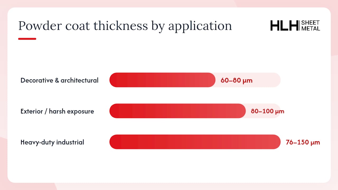
- Decorative and architectural single-coat: 60 to 80 µm (2.4 to 3.1 mils) covers most indoor furniture, fixtures, and lightly exposed parts.
- Exterior and harsh exposure: 80 to 100 µm (3.1 to 3.9 mils) suits window frames, railings, and anything facing UV and weather cycling.
- Heavy-duty industrial: 3 to 6 mils (roughly 76 to 150 µm) applies to agricultural equipment, wheels, and machinery that takes repeated impact or abrasion.
- High-performance and military-grade: ranges climb further under specs like MIL-PRF-24712B, where shipboard components and defense hardware need thicker, tougher films.
A wheel spec and a shipboard bracket spec can look nothing alike, even though both are “powder coated.” The application dictates the number, not habit. That’s why checking a powder’s technical data sheet against the part’s actual service environment beats defaulting to whatever thickness the last job used.
What Coating Thickness Does To Durability And Appearance
Dry film thickness, or DFT, drives four things at once: corrosion resistance, impact and abrasion resistance, gloss and color consistency, and how well the coating follows the substrate’s surface profile. Get it wrong in either direction and you don’t just get a cosmetic issue. You get a part that fails early.
Thin spots, especially at edges, welds, and holes, are where corrosion starts first because the coating simply doesn’t have enough material there to resist moisture and salt exposure over time. Products Finishing’s shop guidance frames this as a two-sided problem: shops that treat DFT as only a minimum threshold miss the equally real risk on the other end.
- Too thin: reduced corrosion resistance, visible substrate show-through, weak spots at sharp edges and fastener holes.
- Too thick: internal stress buildup, cracking, orange peel texture, and slower or incomplete cure through the film.
Practitioner experience puts the ceiling for most decorative powders at roughly 4 to 6 mils, above which cracking risk rises sharply as the film cures. Every powder’s TDS lays out its own tested range, and that document, not a generic rule of thumb, should set your job’s upper and lower bounds.
What Actually Changes Your Film Build During Application
Two shops running the same powder can land in different thickness ranges purely because of application choices. Electrostatic spray, the most common method, depends heavily on gun settings, powder feed rate, and how well the part is grounded. Fluidized bed dipping builds thickness differently and tends to produce heavier, more uniform films suited to different part geometries.
Several variables shift your actual DFT even when your settings stay constant:
- Transfer efficiency: how much sprayed powder actually sticks versus overspray, which shifts with gun voltage and target distance.
- Line speed and preheat: faster lines with insufficient preheat give powder less time to flow and level before cure.
- Part geometry: recesses, corners, and Faraday cage areas (like the inside of a bracket) chronically undercoat versus flat faces.
- Powder chemistry and particle size: finer particle distributions and higher hiding power change how much material is needed to reach full opacity.
- Humidity and ambient temperature: both affect powder flow characteristics and charge retention before the part reaches the oven.
Pro Tip: Run a comb-gauge check on a prototype part before committing the full production run. It takes two minutes and tells you whether your line speed and gun settings are landing in range before you’ve coated fifty parts you’ll have to strip.
How To Measure Powder Coat Thickness Correctly
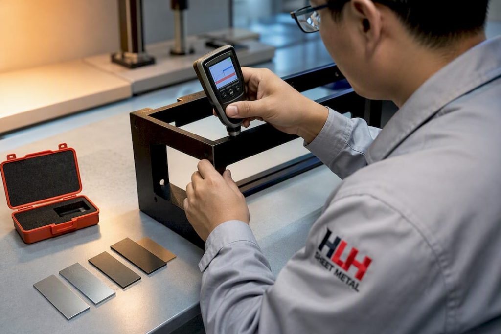
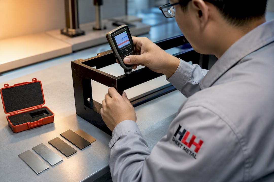
Measurement method depends on what state the coating is in and what substrate sits underneath it. On cured films over steel, magnetic induction gauges are standard. On cured films over aluminum or other non-ferrous metals, eddy current gauges do the job. For non-metal substrates, ultrasonic methods take over. And critically, you don’t have to wait until cure to get a reading.
ASTM D7378 governs measuring uncured powder to predict what the cured thickness will be, and it describes three procedures: comb gauges you drag through wet powder, magnetic or eddy current gauges adapted for uncured film, and non-contact ultrasonic instruments. ASTM D7091 is the reference standard once the part is cured, covering magnetic induction and eddy current measurement of the final dry film.
A basic sampling protocol: take readings across 5 representative areas per part, 3 readings per area, and record the number of readings, mean, minimum, and maximum for each. Calibrate gauges using 1-point or 2-point calibration against certified shims before each shift, and recalibrate whenever you switch powder families, since reduction factors vary by chemistry.
| Method | Substrate | Typical Range/Accuracy | Best Use Case |
|---|---|---|---|
| Magnetic induction | Steel | Cured DFT per ASTM D7091 | Standard cured-film QC on ferrous parts |
| Eddy current | Aluminum, non-ferrous | Cured DFT per ASTM D7091 | Cured-film QC on non-ferrous substrates |
| Non-contact ultrasonic (PosiTest PC) | Uncured powder, any substrate | 20 to 100 µm, ±5 µm accuracy | Predicting cured thickness before oven |
| Comb gauge | Uncured powder | Manual, per ASTM D7378 | Quick prototype and line-speed checks |
| Industrial cured gauge (Elcometer 415) | Ferrous/non-ferrous | Up to 1000 µm, ±0.1 mil, 60+ readings/min | High-volume production QC reporting |
Instrument specs worth requiring from your gauge vendor: stated accuracy, resolution (1 µm is common on good ultrasonic units), and measurement contact area, since a large contact patch on a small part face will give you unreliable averages.
Setting Job Targets And Running QC Without Guesswork
Picking a target isn’t a judgment call, it’s a lookup. Start with the powder’s TDS, cross-reference the applicable spec for the industry (architectural, industrial, military), and factor in the part’s actual exposure. If exposure is severe enough that a single coat can’t reach the needed DFT without risking cracking, specify a two-coat system instead of overbuilding one layer.
- Confirm the target range from the powder TDS and any governing spec before the line runs.
- Run uncured checks per ASTM D7378 on the first parts off the line and adjust gun settings, line speed, or preheat as needed.
- After cure, verify with cured-film gauges per ASTM D7091 across your sampling grid.
- Set acceptance thresholds: average reading within spec, and no single reading below roughly 80% of the minimum spec value.
- Document lot numbers, gauge calibration dates, and any corrective action taken, and flag parts for rework immediately if readings fall outside tolerance.
Pro Tip: Keep a per-powder reduction factor log. Comb-check a prototype, cure it, measure the cured DFT, and divide to get that powder’s shrink ratio. Reuse that number every time you run the same powder instead of re-deriving it from scratch.
Diagnosing Defects Caused By Wrong Thickness
Orange peel texture often traces back to film that’s too thick for the cure schedule, since the powder doesn’t have time to flow out before gelling. Cracking, particularly at edges and corners, points to the same overbuild problem, compounded by internal stress as the film cures unevenly. Adhesion loss and poor hiding, by contrast, usually mean the film is too thin, especially at recesses where spray coverage naturally drops off.
- Orange peel or cracking: reduce film build, slow gun travel less aggressively, or check oven cure profile against the powder TDS.
- Poor hiding or substrate show-through: increase pass count or adjust gun settings for better transfer efficiency rather than just slowing the line.
- Persistent undercoating in recesses: consider a second light pass targeting Faraday cage areas specifically.
In-process fixes work when the defect is caught before full cure. Once a part is fully cured and cracked or shows adhesion failure across a large area, stripping and recoating is almost always faster than trying to patch it.
Powder Coating Standards Worth Knowing
ASTM D7091 and D7378 are the measurement backbone of this entire topic: D7091 for cured film, D7378 for predicting cured thickness from uncured readings. Neither standard sets a required thickness. They set how you measure it, which matters just as much for contractual QC.
- QUALICOAT: architectural specs commonly require a minimum average around 60 µm, with specific measurement location rules.
- AAMA: architectural aluminum specs define their own minima and testing frequency, often referenced alongside QUALICOAT on window and curtain wall projects.
- MIL-PRF-24712B: covers military and high-build coating requirements, where single-coat capability and total film build both get specified more strictly than commercial architectural work.
Always pull the current licensed text of whichever standard governs your contract. Specs get revised, and quoting an outdated minimum on a purchase order is a preventable, expensive mistake.
How HLH Sheet Metal Approaches Thickness In Production
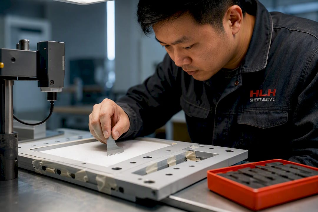
On prototype runs, Comb checks are used to confirm uncured powder targets before committing to full production settings, and threaded holes are masked so film buildup doesn’t interfere with fit. Non-contact uncured readings can help tune line speed in real time rather than discovering a problem after cure. Gauges should be recalibrated per powder family, since reduction factors shift with chemistry.
For parts needing higher total film build, separate primer and topcoat cures may be specified instead of stacking one heavy single coat, to avoid the internal stress that causes cracking down the line. Readers managing their own masking work can check HLH’s powder coat masking guide or browse the fabrication blog for related finishing process notes.
Why Measurement Discipline Beats Chasing A Perfect Number
The biggest mistake in this field isn’t picking the wrong target range, it’s treating thickness as a single minimum to clear rather than a band with a ceiling. Shops that only worry about “thick enough” end up with cracking, orange peel, and wasted powder on the other end of the spectrum. The research bears this out: overbuild causes as many warranty calls as underbuild does, just with a longer delay before the failure shows up.
What gets underrated is the uncured-to-cured reduction factor. Most shops calibrate gauges once, on one powder, and never revisit it when they switch chemistries. That’s backward. A photo-thermal or non-contact reading taken before cure is only as useful as the reduction factor behind it, and that factor changes with particle size, pigment load, and cure schedule. Build a small calibration matrix per powder family and the guesswork mostly disappears.
If there’s one thing to prioritize first, it’s this: measure before cure, not just after. Catching a line-speed problem on an uncured comb check costs you two minutes. Catching it after the oven costs you a stripped batch and a missed delivery date. The instruments exist specifically to move that catch earlier, and too few shops use them that way.
— Nash
FAQ
How Thick Is A 1 Mil Powder Coating?
One mil equals 25.4 µm, so a 1 mil coating is a thin film, well below the typical 2.4 to 3.1 mil (60 to 80 µm) target most single-coat decorative jobs need for full corrosion protection.
What Thickness Does Powder Coating Typically Add To A Part?
Most single-coat decorative and architectural applications add 60 to 80 µm (2.4 to 3.1 mils), while exterior and heavy-duty industrial parts often run 80 µm up to 6 mils depending on exposure and the powder’s TDS.
What Is The MIL Standard For Powder Coating Thickness?
MIL-PRF-24712B governs military and high-build powder coating requirements, specifying thicker, tougher film builds than typical commercial architectural standards for parts facing harsher service conditions.
What Are The Downsides Of Powder Coating?
The main risks are process-related rather than inherent to the coating itself: film that’s too thin loses corrosion resistance at edges and welds, while film that’s too thick risks internal stress, cracking, and orange peel during cure.

