





Table Of Contents

For high-volume progressive die stamping, expect standard features to hold ±0.05 mm and precision features (bearing bores, connector pilot holes, formed heights) down to ±0.01 mm to ±0.02 mm. The single most reliable way to secure those numbers is an explicit punch-to-die clearance specification backed by a tooling dimensional report, first-article CMM data, and running SPC on the dimensions that actually matter. Everything else in the RFQ exists to protect those three things.
TL;DR:
- Precise tolerance requirements depend heavily on feature type and material, with sharp tooling and proper calibration being essential for tight control.
- Punch-to-die clearance should be specified both as a percentage of thickness and an absolute value to avoid interpretation errors and inconsistent execution.
- A detailed verification process, including first-article CMM reports and ongoing SPC monitoring, is crucial to maintain tolerances across millions of parts.
- Selecting a supplier requires matching their tooling, press capacity, and quality systems to your tolerance needs, with direct evidence verification more reliable than certification alone.
- Regular maintenance, pilot wear tracking, and press condition monitoring are necessary to prevent tolerance drift during high-volume runs.
Realistic Stamping Tolerance Targets By Feature And Material
Tolerance expectations shift depending on what kind of feature you’re holding and what material is running through the press. A blanked outer profile behaves nothing like a pierced hole 0.5 mm from a bend line, and a 5052 aluminum strip springs back differently than 301 stainless at the same thickness.
As a working baseline for progressive die work at typical production thicknesses (0.2 mm to 3 mm):
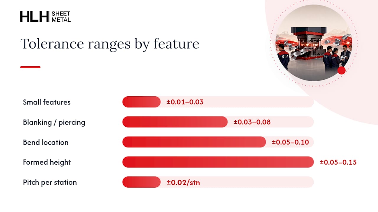
- Blanking/piercing (hole diameter, outer profile): ±0.03 mm to ±0.08 mm, tighter on thinner stock with sharp, well-maintained tooling.
- Formed height (bosses, dimples, embosses): ±0.05 mm to ±0.15 mm, driven mostly by material springback and die wear, not punch accuracy.
- Bend location relative to a datum: ±0.05 mm to ±0.10 mm, worse if the bend crosses grain direction on a textured material.
- Small electronic/connector features (pilot holes, tab widths): ±0.01 mm to ±0.03 mm, achievable only with ground or EDM tooling and pilot correction stations.
- Pitch/center distance across multiple stations: cumulative error typically held under ±0.02 mm per station when pilots are properly maintained.
Material selection drives a lot of this before the tool is even cut. Coil thickness tolerance (a mill-certified ±0.01 mm sheet behaves very differently from a commodity ±0.03 mm coil), tensile and yield strength, and grain direction all change how a part springs back after forming. A 0.5 mm cold-rolled steel part bent across the grain will hold tighter angle tolerance than the same part bent with the grain, because the grain structure resists the fold more uniformly.
The costliest mistake engineers make on the drawing is applying a blanket ±0.02 mm to every dimension because it looks safer. It isn’t. It inflates tooling cost, slows die tryout, and forces suppliers to quote conservatively because they assume you’ll enforce it everywhere. Specify tight tolerances only where the part’s function actually requires them (mating surfaces, electrical contact points, assembly interfaces) and let non-critical dimensions ride on the general tolerance standard named on the drawing.
Punch-to-die Clearance, Pilot Design, And Pitch Control
Punch-to-die clearance is the highest-leverage number on the entire tool build. Too tight and you get galling, premature punch wear, and heat buildup; too loose and you get burrs, slugging, and dimensional drift as the tool ages. Yet it’s the spec buyers most often leave to the supplier’s discretion.
State clearance two ways on the drawing, not one. Naming both a percent-of-thickness clearance and an absolute millimeter value closes the ambiguity gap that otherwise triggers rounds of clarification emails during quoting. A supplier reading “8% of stock thickness” alone might round differently than you intended on a 0.3 mm part; give them the absolute number too.
Three things determine whether that clearance spec actually holds through a production run:
- Pilot repeatability. Pilots register the strip at each station, and their wear directly drives hole-location tolerance. Ground or wire-EDM pilots hold registration far longer than turned pins, especially past a few million hits.
- Pitch accuracy across stations. Cumulative pitch error compounds station by station. If station three drifts 0.01 mm and station seven drifts another 0.01 mm in the same direction, your final feature-to-feature tolerance has already doubled before you’ve inspected a single part.
- Pilot maintenance cadence. Mist-lubricated carbide pilot pins combined with slow-feed wire EDM construction are common in tighter multi-station builds, and they hold matrix and pilot mating tolerances to a fraction of what turned steel pins manage over the same run length.
Pro Tip: *Ask your toolmaker for the actual clearance measurement taken on the finished die, not just the design intent.
Pitch control deserves its own line item on the tooling dimensional report. Request center-distance measurements between every station, not just station one to station N. A tool that’s dead accurate station to station but drifts consistently in one direction will still produce parts that fail a total-length check, even though every individual pitch measurement looks fine in isolation.
Die Construction: Tool Steel, EDM Accuracy, And Maintenance
Tooling accuracy is where tolerance promises either get built into the die or get lost forever. The steel you request, the machining method used to cut it, and the maintenance schedule you agree to all set a ceiling on what the die can deliver, no matter how good the press is.
For tight-tolerance progressive work, specify tool steel by hardness and application, not by generic “hardened steel” language:
- D2 or SKD11 (58 to 62 HRC) for general blanking and piercing punches, a common baseline for medium-to-high volume runs.
- Powder metallurgy (PM) steels like ASP23 or CPM 10V for abrasive materials or runs exceeding several million hits, where conventional D2 wears faster than acceptable.
- Carbide inserts on the highest-wear cutting edges, particularly for stainless or high-silicon aluminum stock that abrades standard tool steel quickly.
- Thick die shoes and guided-post construction to resist deflection under press tonnage, which matters more than most buyers assume once shut height and ram parallelism enter the picture.
Wire EDM and slow-feed EDM cut punch and cavity profiles to a level of geometric accuracy that conventional milling can’t match, especially on small radii and pilot bores. Finish grinding on cutting faces should target a surface roughness around Ra 0.4 to Ra 0.8 micrometers; rougher finishes accelerate galling and shorten the interval between regrinds.
Coatings matter more on abrasive or gummy materials. TiN or TiCN coatings on punches reduce galling on stainless and aluminum, extending the run length between sharpenings. Stripper plate design (guided vs. spring-loaded, and the clearance built into stripper bushings) affects burr consistency as much as the punch itself, so it deserves the same scrutiny on the drawing package.
None of this holds up without a maintenance schedule. Tooling uptime and die-life targets should be specified as a hit count before first regrind, not left as a vague “as needed” clause. A die spec’d for 500,000 hits before regrind and pushed to 800,000 without service is exactly how a supplier ends up shipping parts with burr growth nobody caught until the customer’s incoming inspection flagged it.
Press Control And In-process Monitoring That Prevent Drift
A perfectly built die still drifts if the press running it isn’t controlled. Ram parallelism, shut height consistency, feeder accuracy, and strokes per minute all interact with tooling wear and material behavior in ways that show up as slow, creeping tolerance loss rather than a sudden failure.
Ask suppliers to record and share these press metrics on request, not just at FAI:
- Ram parallelism, typically held within 0.01 mm to 0.02 mm across the bed on presses running precision work.
- Shut height repeatability, checked at setup and periodically through long runs since thermal expansion in the press frame shifts shut height as the machine heats up.
- Feeder accuracy, since a servo feed holding pitch to a few microns behaves very differently from a mechanical roll feed under load.
- Strokes per minute, because running faster than the die and material combination tolerates increases heat generation and accelerates wear.
Statistical process control needs to be applied to specific, named dimensions rather than “the whole part” as a vague blanket instruction. Pick the two or three features that matter most functionally, chart them with defined sampling intervals (every 500 parts is a common cadence on stable runs, tighter on new tooling), and set control limits that trigger action before parts drift out of spec, not after.
A quick way to think about the stakes: interchangeability at production scale depends on holding process variation inside a specified band, which is the entire premise behind mass production as a manufacturing model. A single out-of-control dimension anywhere in the process undermines that interchangeability across the whole run, not just the parts measured.
Environmental and handling factors compound press-level variation. Strip tension that varies because of a poorly set decoiler introduces feed inconsistency the press can’t correct for. Lubricant contamination or inconsistent application changes friction at the punch face, which shifts clearance behavior even though the tool itself hasn’t changed. These aren’t glamorous variables, but they’re the ones that turn a capable die into an inconsistent one.
The RFQ And Drawing Checklist That Prevents Tolerance Disputes
Most tolerance disputes with Chinese stampers trace back to one root cause: the drawing left something open to interpretation, and the supplier’s default filled the gap differently than the buyer expected. A tight checklist closes that gap before quoting even starts.
- Name a tolerance standard explicitly. State ISO 2768-m (or the appropriate class) or GB/T 13914-2013 for every dimension without an individual callout. Leaving this blank is the single most common cause of cross-border tolerance mismatches, since suppliers fall back to whichever national standard they default to internally when a drawing doesn’t specify one.
- Give numeric tolerances for every functionally critical feature. Don’t rely on a general note to cover mating surfaces, bore diameters, or assembly interfaces.
- Attach a material specification with a mill test report (MTR) requirement. Reference ASTM grade designations where applicable so incoming material is verifiable against the print, not just “similar to.”
- Specify surface and edge conditions. Burr height limits, deburr requirements, and any plating or finish spec need explicit numbers, not “clean edge” language.
- Require an FAI with a full CMM report covering every critical dimension, tied to PPAP-style documentation where the program calls for it.
- Name the SPC dimensions and sampling frequency you expect charted through the production run, not just at first article.
- State expected production volume and die-life target (hits before regrind) so the supplier quotes appropriate tool steel and construction.
- Define trial-run acceptance gates, including who owns scrap and regrind costs if the first production run doesn’t meet spec.
Skipping even one of these tends to surface as a dispute week into production, not at quoting, which is the worst time to discover a misunderstanding.
Verification That Actually Proves Tolerance Over Millions Of Hits
A tolerance spec on paper means nothing until it’s verified against real parts, repeatedly, across the length of a production run. First-article inspection is the starting gate, not the finish line.
An FAI CMM report worth trusting includes every dimension called out on the drawing, measured against the actual datum scheme specified, with pass/fail status against each tolerance. This document is what feeds a PPAP submission package, and it’s the baseline every later SPC chart gets compared against. If the FAI report is vague or incomplete, everything downstream inherits that uncertainty.
- Inline inspection (in-die sensors, vision systems) catches drift within the same run but adds tooling cost and complexity.
- Offline inspection (periodic CMM pulls) is cheaper and more flexible but leaves gaps between samples where bad parts can accumulate before detection.
- Most high-volume programs land on a hybrid: inline go/no-go gauging for critical features, offline CMM audits at defined intervals for full dimensional confirmation.
A sampling plan tied to CPK targets, rather than a flat “check one part per hour” rule, adapts naturally as the process proves itself stable. Early in a run, sample more; once CPK on the critical dimensions holds comfortably above 1.33 across several thousand parts, sampling frequency can relax.
Mid-run practicality: four-point clearance verification (measuring burr and slug condition at four positions around a cut feature) catches punch wear before it shows up as an out-of-spec dimension, giving line operators an early warning that beats waiting for a CMM flag. Combine that with scheduled mid-run audits at fixed hit-count intervals, and you have a defensible reason to stop the line for a regrind before scrap accumulates instead of after.
Matching Supplier Tier To Your Tolerance Requirements
Not every Chinese stamping supplier operates at the same level, and ISO 9001 certification alone doesn’t reliably predict day-to-day process discipline. Export-tier plants running APQP, FMEA, and daily SPC deliver far tighter, more consistent PPM than smaller shops leaning on final sorting to catch defects.
- Small precision shops: capable of very tight tolerances on low volumes, but toolroom capacity and press count may not scale to millions of parts without lead-time risk.
- Mid-tier exporters: solid balance of tolerance capability and volume, typically the sweet spot for most OEM programs, but audit their SPC evidence directly rather than trusting certificates alone.
- Large export plants: built for volume and consistency, with formal APQP/PPAP systems, though tolerance capability on unusually small or delicate features sometimes trails specialist shops.
Audit for press tonnage range, toolroom equipment (grinding, EDM), documented FMEA and SPC practice, and verifiable customer references before committing tooling investment. Structure acceptance gates and scrap/regrind responsibility into the contract up front, tied to the tolerance and cost tradeoffs you’re willing to accept for the program’s volume and margin.
How HLH Sheet Metal Runs High-volume Tolerance Programs
A tolerance program only works if the workflow behind it is disciplined from the first drawing review to the millionth part. HLH SHEET METAL structures every progressive-die program the same way:
- DFM review against the drawing’s named tolerance standard before tooling design starts.
- Tooling spec sign-off covering clearance, pilot design, and steel selection.
- Die tryout with dimensional verification before production release.
- FAI with full CMM report against every critical dimension, feeding PPAP documentation.
- SPC ramp-up on named critical features once production volume stabilizes.
That process runs across ISO-certified facilities with in-house toolrooms, so engineers preparing an RFQ can attach drawings, target volumes, and die-life expectations directly and get a quote that already accounts for tooling accuracy rather than a rough estimate.
What Actually Moves The Needle On Tolerance Control
Most advice on this topic treats every control lever as equally important, and that’s the part I’d push back on. Punch-to-die clearance and a named tolerance standard on the drawing do more work than the rest of the checklist combined, because they eliminate the ambiguity that causes most disputes before a single part gets cut.
Certifications get overrated. A wall of ISO paperwork tells you a supplier has a documented system somewhere; it doesn’t tell you whether SPC charts are actually being pulled on the dimensions you care about at 2 a.m. on a third shift. Ask for the tooling dimensional report and a real FAI CMM package before you ask about certificates.
The conventional advice also underrates thermal drift and pilot wear on long runs. Engineers spec the die build carefully, then treat the press and maintenance schedule as an afterthought. Tolerance loss on a five-million-hit run rarely comes from a bad die design. It comes from nobody tracking when the pilots were last replaced.
Prioritize the drawing standard and clearance spec first, verification second, certifications last. That order reflects where tolerance failures actually originate, not where they get discovered.
— Nash
Get A Progressive Die Stamping Quote Built Around Your Tolerance Requirements
HLH SHEET METAL runs progressive die programs on in-house tooling, backed by ISO-certified quality systems and CMM/FAI/SPC deliverables built into the workflow instead of bolted on after a customer complains. Press ranges cover both prototype-volume trial runs and full production tonnage, so a program can move from first article to millions of hits without changing suppliers mid-project. That continuity is the real advantage over splitting tooling and production across separate vendors: no re-validation gap, no second FAI cycle, no renegotiating who owns scrap when volume ramps.
To get the fastest, most accurate quote, attach your drawing with a named tolerance standard, material spec, target volume, and expected die-life requirement. Request a quote through the sheet metal stamping capabilities page and a technical reviewer will confirm clearance specs and tooling approach before tooling design begins.
FAQ
What Tolerance Can I Expect From Progressive Die Stamping?
Standard blanked and pierced features typically hold ±0.03 mm to ±0.08 mm, while precision features like small connector holes can reach ±0.01 mm to ±0.03 mm with ground or EDM tooling and proper pilot control.
Should I Specify ISO 2768 Or GB/T 13914 On My Drawing?
Name one of them explicitly rather than leaving the tolerance standard blank; drawings without a named standard often get defaulted differently by suppliers, causing tolerance disputes after tooling is already cut.
How Should Punch-to-die Clearance Be Specified?
State it both as a percentage of material thickness and as an absolute millimeter value, since relying on percentage alone leaves rounding open to interpretation during quoting.
What Does An FAI CMM Report Need To Include?
Every critical dimension on the drawing measured against the specified datum scheme with a clear pass or fail status, since this document also feeds PPAP approval and becomes the baseline for later SPC comparisons.
How Do I Choose The Right Tier Of Chinese Stamping Supplier?
Match press tonnage range and toolroom capability (grinding, EDM) to your feature tolerances, then verify APQP, FMEA, and SPC evidence directly rather than relying on ISO 9001 certification alone.
What Causes Tolerance Drift During Long Production Runs?
Pilot wear, thermal expansion in the press frame, and clearance changes from tool wear are the most common causes; scheduled regrind intervals and mid-run dimensional audits catch drift before it produces scrap.

