



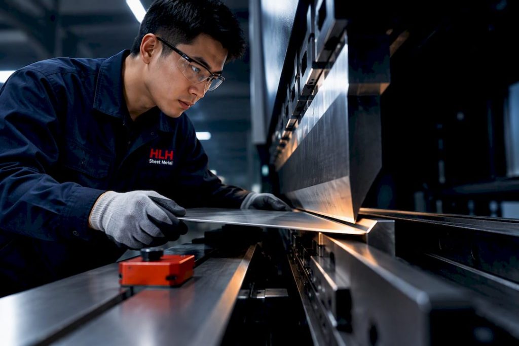

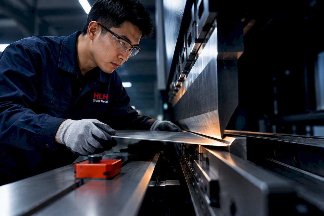
Press brake bending forms sheet or plate by pressing an upper punch into a lower die, creating a controlled angle along a straight line. For most jobs, air bending gives you the best flexibility since one tool set produces multiple angles. Reserve bottoming or coining for parts where tolerance stack-up can’t tolerate springback drift. All three methods are commonly run daily across ISO-certified production lines, and the difference between a scrapped part and a good one often depends on the selected method and how well springback is accounted for.
TL;DR:
- Proper setup and tooling choices are critical, with a focus on die shoulder contact of around 70 percent of the V-opening to prevent flange cracking or shifting.
- Using air bending is suitable for mixed production runs but requires careful compensation for springback, especially with inconsistent materials.
- Selecting the correct press brake type depends on tolerance needs, run length, and part complexity, with CNC controls offering significant setup time reductions.
- Estimating bending force accurately involves calculations that include material strength and die opening, with a safety margin of 20 to 30 percent to account for variation.
- Investing in angle-sensing feedback and servo-electric drives benefits high-mix shops with tight tolerance parts but standard tooling discipline and QA yield more cost savings for consistent, long-run production.
What Actually Happens Inside A Press Brake During Bending
A punch descends into a V-die, and the sheet deforms plastically around a line called the neutral axis, the layer inside the material that neither stretches nor compresses. Material above that axis stretches; material below it compresses. Once the punch retracts, the metal relaxes slightly toward its original shape. That relaxation is springback, and it’s why a 90 degree programmed bend often measures 91 or 92 degrees off the machine.
Every press brake job starts with a handful of machine specs that determine what’s physically possible. Get these wrong and you either can’t make the part or you damage the tooling trying.
- Tonnage — the maximum force the ram can apply, which sets the ceiling on material thickness and bend length you can form.
- Working length — the usable width of the bed, which limits how long a single bend line can be.
- Stroke — the vertical travel distance of the ram, affecting cycle speed and clearance for part removal.
- Throat depth — the distance from the front of the machine to the frame, which governs how deep a box or channel shape you can form before the part collides with the structure.
- Open height — the gap between the ram and bed at full retraction, which determines how much clearance you have to load and remove parts.
- Back-gauge range — how far the positioning fingers can travel front to back, setting the maximum flange length the machine can produce in one pass.
On CNC machines, the back gauge doesn’t just sit in one spot. It repositions automatically between bends, sequencing a multi-bend part without the operator re-measuring each flange. Higher-end setups add angle-sensing systems that measure the actual bend angle mid-stroke and adjust ram depth in real time, correcting for material variation before the part ever leaves the machine. That closed-loop correction is what separates a shop running by feel from one running by data.
Which Press Brake Type Fits Your Production Run?
The machine class you choose drives everything downstream, from cycle time to tolerance ceiling. Four categories dominate the market, and each one solves a different problem.
- Hydraulic press brakes — the workhorse of most fabrication shops, offering high tonnage, synchronized dual-cylinder rams, and solid repeatability at a moderate capital cost.
- Mechanical press brakes — older technology using a flywheel and clutch, fast but less flexible, mostly found in legacy operations running one part number for years.
- Servo-electric press brakes — driven by electric servo motors instead of hydraulic fluid, delivering faster cycles, lower energy draw, and tighter repeatability, though at a higher upfront price.
- Hybrid brakes — combine hydraulic force with servo-electric control for a middle ground between raw tonnage and precision positioning.
CNC controls turn any of these into a programmable system. A non-CNC brake relies on the operator to set backgauge position and ram depth manually for every bend, which works fine for short runs but invites drift on complex parts. A CNC brake with a multi-axis back gauge (typically X, R, and Z travel) can reposition automatically between bends and store programs for repeat jobs, cutting setup time dramatically on parts with five or more bend lines.
When picking a machine class, weigh three factors: how tight your tolerance requirement is, how long your production run will be, and whether your part geometry includes tight-radius or offset bends that demand extra axis control. High-mix, low-volume shops usually lean servo-electric or hybrid for the flexibility. Long, single-part runs still favor mechanical or hydraulic for raw throughput.
How Do You Choose The Right Bending Method?
Method selection is where most quoting mistakes happen. Pick the wrong one and you either overpay for tooling you didn’t need or under-deliver on accuracy the part actually requires.
- Air bending forms the part without the punch fully seating the material into the die, using a V-opening typically 6 to 10 times the material thickness. It’s the default choice for mixed-run production because one die can produce a range of angles just by adjusting ram depth. The tradeoff is springback sensitivity: angle accuracy typically lands within plus or minus half a degree to a full degree, and that variance grows with inconsistent material.
- Bottoming presses the material fully against both punch and die walls, squeezing out most of the springback and holding tighter angle tolerance than air bending. It requires tooling matched precisely to the target angle and radius, since you’re now forming to the die’s exact geometry rather than a programmed depth.
- Coining goes a step further, applying enough force (often 5 to 8 times bottoming tonnage) to actually thin and reshape the material at the bend line. Accuracy improves again, but tooling wear accelerates and press capacity requirements jump substantially.
- Three-point and rotary bending use a moving bottom die or rotating die element to control the bend with less tool marking, useful for pre-finished or coated materials where surface cosmetics matter.
- Folding and wiping clamp the sheet and fold it over a beam rather than pressing it into a V, common on architectural panels and thin-gauge parts with long flange requirements.
- Urethane bending replaces steel dies with a urethane pad, protecting painted or polished surfaces from tool marks at the cost of die life and precision.
A quick worked example shows how sensitive air bending is to setup: increasing the V-die opening on the same material thickness reduces the required tonnage by a significant amount, but the springback angle typically increases correspondingly because the material bends over a wider unsupported span. That’s the trade you’re always making with air bending: less force and more flexibility in exchange for a wider springback window.
Pro Tip: If a part has a mix of critical and non-critical angles, don’t force the whole job into coining just to hit the one tight tolerance. Bottom that single bend and air-bend the rest; you’ll save tooling wear and press time without sacrificing the spec that matters.
As a general rule: default to air bending unless a specific angle tolerance, cosmetic requirement, or repeatability spec tells you otherwise.
Getting Tooling And Fixtures Right
Punches come in sharp, standard-radius, and gooseneck profiles, each suited to different part geometries, gooseneck punches in particular let you clear formed flanges on box-style parts without hitting the machine frame. Dies are selected primarily by V-opening width, since that width, combined with punch radius, determines the achievable inside bend radius on the finished part. A narrower V-die tightens the possible radius but demands more tonnage; a wider one relaxes force requirements but limits how small a radius you can form.
Minimum flange length is where a lot of engineering drawings quietly fall apart. The rule of thumb many shops use is “4T plus the bend radius,” but that shortcut only holds if the die shoulders actually have room to support the material. The Fabricator’s tooling guidance notes that a flange needs to contact roughly 70 percent of the V-opening on a standard die, and acute-angle dies demand even more contact area. A flange that satisfies the 4T rule on paper can still snap into the die or shift the bend line if it doesn’t have enough shoulder support, which is exactly why flange checks belong in DFM review, not just final inspection.
Statistic Callout: Die shoulder contact of roughly 70 percent of the V-opening is the baseline, The Fabricator cites for standard V-dies. Acute dies require more, which means a “safe” flange on a standard die can fail on a tighter die without redesign.
Before running a job, walk through these setup checks every time:
- Confirm X and Z axis alignment on the back gauge before the first piece runs.
- Verify the die is fully seated and square in the bed, not just resting against the clamp.
- Check back-gauge finger position against the programmed flange dimension, not just the CAD drawing.
- Inspect punch and die edges for nicks or wear that will transfer marks onto every part in the run.
How Do You Calculate Bend Allowance And Bending Force?
Two formulas govern almost every quoting and setup decision on a press brake job: bend allowance and bending force. Get the K-factor wrong and your flat pattern is wrong before the part ever touches the machine.
- Bend allowance (BA) is the length of material consumed by the bend itself, calculated as BA = Angle × (π/180) × (Radius + K-factor × Thickness). The K-factor represents where the neutral axis actually sits relative to material thickness, and it typically ranges from 0.3 to 0.5 depending on material, thickness, and bend method. Air bending tends toward the lower end of that range; bottoming and coining push it higher because the material is compressed more fully into the die.
- Bend deduction (BD) tells you how much to subtract from the sum of your flange lengths to get the correct flat pattern length, and it’s derived directly from bend allowance once you know your outside setback.
- Minimum inside bend radius generally runs from about 0.8 times material thickness to 2 times material thickness for mild steel, though the actual achievable radius always depends on your specific die width and punch profile, not just the material spec sheet.
- Bending force can be estimated with F = (K × S × T² × L) / V, where S is material tensile strength, T is thickness, L is bend length, V is the V-die opening, and K is a process constant (roughly 1.33 for air bending). Run a quick example: a 4-foot bend in 0.125-inch mild steel with a 1-inch V-opening lands in the neighborhood of 15 to 20 tons required, depending on the exact tensile strength of the coil. Always build in a safety margin of 20 to 30 percent above your calculated tonnage since material lot variation is real.
| Calculation | Formula | Typical range |
|---|---|---|
| K-factor | Neutral axis position ratio | 0.3 to 0.5 |
| Minimum inside radius (mild steel) | Die and punch dependent | 0.8T to 2T |
| Air bend V-opening | Multiple of thickness | 6T to 10T |
| Coining force multiplier | Vs. bottoming tonnage | 5x to 8x |
Springback compensation gets folded into the setup by either overbending the programmed angle a degree or two beyond target, or by using an angle-sensing system that measures the actual result mid-cycle and adjusts ram depth automatically. For a deeper walkthrough of K-factor selection by material, HLH SHEET METAL’s K-factor guide breaks down values by alloy and thickness.
What Mistakes Cause The Most Scrap And Injuries?
Most bad parts trace back to one of a small handful of repeat offenders, and most of them are avoidable with a five-minute check before the first hit.
- Using the wrong die width for the specified inside radius, which either overstresses the material or produces an oversized radius.
- Specifying a flange shorter than the die can actually support, leading to the flange snapping into the V-opening mid-bend.
- Ignoring grain direction on brittle or high-strength alloys, which causes cracking along the bend line instead of a clean fold.
- Improper clamping that lets the sheet shift during the stroke, throwing off the entire bend sequence on multi-bend parts.
When springback or misalignment shows up on the shop floor, the fastest fix is usually recalibrating the angle-sensing feedback or rechecking back-gauge squareness before assuming the material itself is at fault.
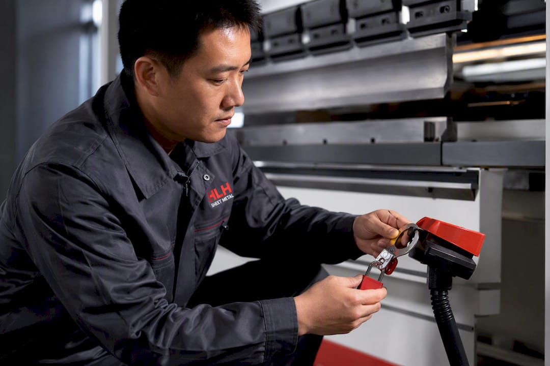
Safety controls matter just as much as accuracy. OSHA’s guidance on powered press brakes calls for point-of-operation guarding, presence-sensing devices, two-hand controls, and pullback or restraint devices on operators working close to the die. Lockout/tagout procedures are mandatory during tooling changes and maintenance. OSHA’s guidance also flags a hazard operators tend to underestimate: unexpected workpiece movement, not just finger entrapment, causes injuries when a part springs or shifts unpredictably mid-cycle.
Pro Tip: Foot pedal accidents happen more often during tooling changes than during production runs. Disconnect or lock out the pedal circuit any time hands are near the die, even for a “quick check.”
How HLH SHEET METAL Applies These Standards In Production
Press brake bending is run across multiple ISO-certified plants in China, where tooling checks and setup discipline similar to the above are daily standards.
- Rapid prototyping runs can let engineers validate bend allowance and springback assumptions before committing to full production tooling.
- Angle-sensing feedback and calibrated back-gauge sequencing can help catch springback drift before it becomes scrap across a production batch.
- Multi-plant capacity can support both single-prototype orders and volume production runs without switching vendors mid-project.
- An English-speaking support team may review flange and tolerance callouts with engineers directly, catching DFM issues before tooling is cut.
Where Should Shops Actually Invest To Improve Bending Accuracy?
Angle-sensing and servo-electric drives pay back fastest on high-mix shops running frequent tolerance-critical parts, not on shops running the same three part numbers for years. Tooling standardization and QA discipline usually save more money than a tonnage upgrade ever will. A shop with sloppy die management on a premium machine still produces inconsistent parts.
— Nash
Ready To Move Your Bending Job Into Production?
Getting bend allowance, springback compensation, and die selection right on paper is only half the job. Engineering is turned into finished parts by running air bending, bottoming, and coining across ISO-certified plants built to handle both single prototype and full production runs without changing vendors. That combination matters most when a design goes through several revisions before it’s ready to scale, since re-tooling and re-quoting with a new supplier each time adds weeks that most projects can’t spare. Our sheet metal bending services cover everything from V-die selection to angle-sensing feedback on the machine, backed by an English-speaking engineering team that reviews flange and tolerance callouts before tooling gets cut. If your drawing has a bend that’s hard to quote elsewhere, send it over and request a quote through our sheet metal fabrication capabilities page.
Sources
For engineers verifying the calculations and safety points above: OSHA’s press brake safety guidance, The Fabricator’s tool selection rules, TRUMPF’s bending tools operator supplement, and Wikipedia’s bending (metalworking) overview each cover a piece of the process referenced throughout this guide. Readers preparing formal bend schedules for construction or structural work can also reference shop drawing and bar bending schedule production for documentation standards outside metal fabrication.
FAQ
What Is Press Brake Bending?
Press brake bending is a metal forming process where an upper punch presses sheet or plate into a lower V-die to create a controlled angular bend. Machine capacity is defined by tonnage, working length, stroke, and back-gauge range, and CNC controls sequence multiple bends automatically on complex parts.
What Is The Rule Of 8 On A Press Brake?
The rule of 8 refers to sizing the air-bending V-die opening at roughly 8 times the material thickness, a common starting point for balancing tonnage requirements against achievable bend radius. It’s a starting reference, not a fixed law. Actual die selection should still be checked against die shoulder contact and the target inside radius for the specific part.
How Do I Calculate The Bending Force For A Press Brake?
Bending force for air bending is commonly estimated with F = (K × S × T² × L) / V, where S is tensile strength, T is thickness, L is bend length, and V is the V-die opening. Build in a 20 to 30 percent safety margin above the calculated tonnage to account for material lot variation.
What Is The Minimum Bend Radius For A Press Brake?
Minimum inside bend radius for mild steel typically falls between 0.8 and 2 times the material thickness, though the true minimum always depends on the specific die width and punch profile in use. Die geometry, not just the material spec sheet, sets the real limit, so it’s worth checking against a dedicated minimum bend radius reference before finalizing a design.
Does HLH SHEET METAL Offer Press Brake Bending Services?
Yes, HLH SHEET METAL provides press brake bending as part of its sheet metal fabrication services, covering prototyping through volume production across ISO-certified plants. Pricing depends on part geometry, material, and volume, and current quotes are available directly through the site.
Recommended
- K-Factor Bending: The Engineer’s Guide to Accurate Bend Allowance
- Sheet Metal DFM: A Practical Design Guide for Engineers
- Minimum Bend Radius: Practical Guide for Engineers

