




Table Of Contents
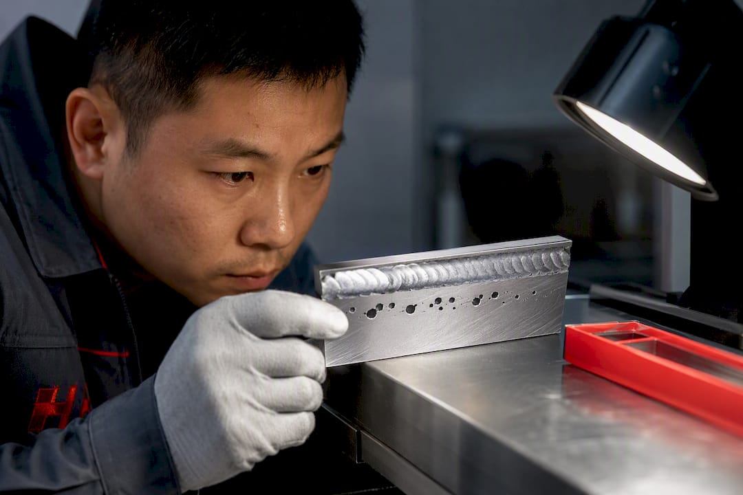
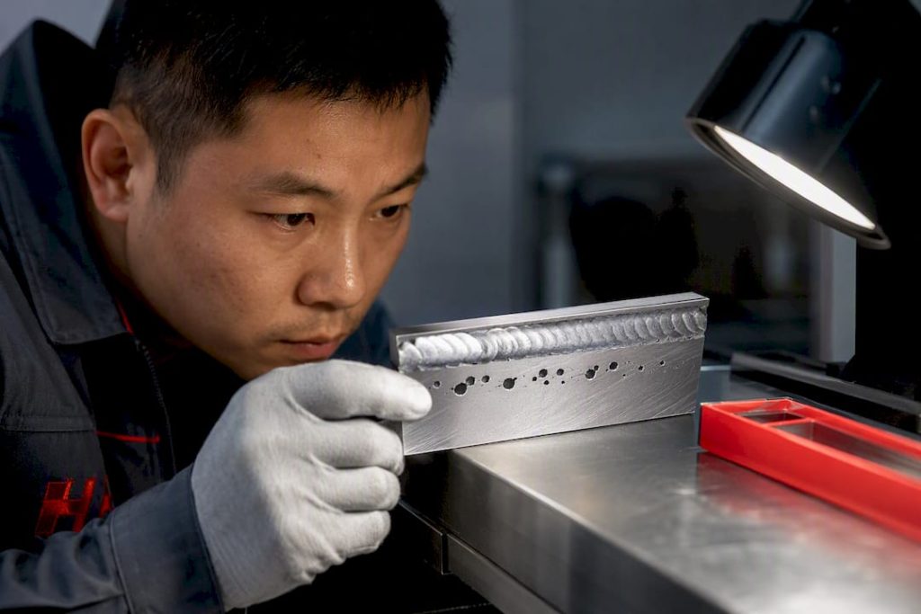
Aluminum weld porosity comes almost entirely from hydrogen absorbed into the molten pool during welding, gas that gets trapped as bubbles when the metal solidifies too fast for it to escape. The top-priority control is not tighter parameters, it’s hydrogen elimination: clean base metal, dry filler, low dew-point shielding gas, and a process setup that gives trapped bubbles time to rise out before the pool freezes.
TL;DR:
- Most aluminum weld porosity results from hydrogen trapped during welding, which is caused by contamination, moisture, or inadequate gas quality.
- Detection of subsurface porosity requires radiography or computed tomography, especially for load-bearing and fatigue-critical parts.
- Proper cleaning, dry filler, low dew-point shielding gas, and process tuning to allow bubble escape significantly reduce porosity risks.
- Hybrid GMAW-GTAW welding and pulsed modes can help mitigate porosity by promoting bubble escape and reducing trapping.
- Acceptable porosity limits depend on project standards, but minimizing hydrogen sources through strict handling protocols is essential for quality welds.
What Causes Aluminum Weld Porosity? The Hydrogen Mechanism
Liquid aluminum holds roughly twenty times more dissolved hydrogen than solid aluminum does at the same temperature. The moment the weld pool starts to solidify, that solubility gap forces the excess hydrogen to come out of solution. If it can’t escape upward through the liquid metal fast enough, it gets frozen in place as a bubble, and that bubble is porosity.
Where those bubbles form and how far they travel before freezing depends on both alloy and process. In-situ radiography of live weld pools shows that macro-pore nucleation sites shift with alloy composition and travel speed. Slower travel and higher hydrogen content both push pores to grow larger before the freezing front catches them, according to thesis research using in-situ radiography. Two forces drive pore movement inside the pool:
- Buoyancy pushes bubbles upward toward the surface, where they can vent before solidification.
- Marangoni convection, driven by surface tension gradients across the pool, can drag bubbles sideways or even downward, trapping them deeper in the weld.
- Pool flow direction near the leading edge versus the trailing edge changes where pores tend to cluster.
Micro-porosity (pores under roughly 0.5 mm) rarely shows up on visual inspection and usually has a minor effect on strength unless it’s dense. Macro-porosity is a different story: it concentrates stress and can be the starting point for fatigue cracks, which is why testing shows porosity meaningfully lowers fatigue life in aluminum welds even when a weld looks clean from the outside.
How Do You Detect And Measure Weld Porosity?
Visual inspection catches surface-breaking pores and gross clustering, and it’s adequate for low-consequence, non-structural aluminum parts. It tells you nothing about subsurface porosity, which is where the real fatigue risk usually hides.
For anything load-bearing or fatigue-critical, you need a method that sees inside the weld:
- Radiography reveals pore count, size distribution, and area fraction across the weld cross-section, giving you a quantifiable defect map instead of a guess.
- Computed tomography (CT) goes further, reconstructing 3D pore location and volume, which matters most in dissimilar-metal or cast-to-sheet joints where CT studies show pores cluster disproportionately near the cast material.
- Ultrasonic testing (UT) is faster for field inspection and works well on thicker sections where radiography access is limited.
- Nick-break testing is destructive but cheap, useful for qualifying a WPS before production runs, not for verifying finished parts.
Whatever method you choose, write it into the contract. Acceptance criteria under codes like AWS D1.2 specify maximum pore size and linear porosity limits, and the project documentation should state exactly which inspection method applies and what “pass” means before the first weld gets struck.
Shop-floor Prevention: Cleaning, Filler, Gas, And Parameters
Most porosity problems trace back to handling, not metallurgy. NASA’s early but still-relevant welding research found base-metal composition plays a smaller role than surface contamination and atmospheric pickup during handling, meaning the fix usually sits in your prep routine, not your alloy spec, according to the NASA program report on porosity causes.
- Clean in the right order. Solvent degrease first to strip oils and hydrocarbons, then mechanically remove the oxide layer with a dedicated stainless steel brush, one that never touches carbon steel. Weld within minutes of brushing; the hydrated oxide layer starts rebuilding the moment bare aluminum meets humid air.
- Store filler and wire dry. Keep spools sealed until use, and if your shop has had recurring porosity, consider a bake protocol for wire that’s been exposed to humidity. Inspect the feed path, contact tip, and liner regularly. A worn liner collects moisture and debris that gets fed straight into the arc.
- Control shielding gas hygiene. Aim for a low dew point, keep gas lines as short as practical, and purge new lines before welding. TWI’s guidance on aluminum porosity recommends checking the entire gas system for leaks and moisture ingress rather than assuming the bottle is the only variable. Argon-helium blends can also change bubble escape behavior in the pool, an underused lever worth testing on stubborn joints.
- Tune your parameters for escape time, not just penetration. Shorter arc length, appropriate travel speed, and pulsed current all give bubbles more time to rise before the pool freezes. Preheat or slightly higher energy input can help on thicker sections where the pool stays liquid longer.
- Watch your environment. Drafts near open bay doors disrupt shielding gas coverage. Grinding dust or oil mist from a nearby process can settle on parts waiting to be welded.
Pro Tip: Keep a dedicated brush, glove set, and storage bin for aluminum only. Cross-contamination from steel shops is one of the most common and most preventable sources of chronic porosity, and it’s invisible until you’ve already welded a bad batch.
Does Your Welding Process Change The Porosity Risk?
GTAW and GMAW both depend heavily on filler cleanliness and surface prep, since hydrogen mostly rides in on the wire and the base metal oxide layer. Pulsed modes help here because the current cycling agitates the pool, giving bubbles more chances to reach the surface before freezing.
- Laser and keyhole welding introduce a different failure mode: even with hydrogen fully controlled, an unstable keyhole can collapse and trap gas mechanically. Beam stability and consistent shielding gas flow matter as much as cleanliness in these processes.
- Hybrid GMAW-GTAW setups can actually cure porosity mid-weld. The trailing GTAW arc’s oxide-cleaning and remelt action gives trapped bubbles a second chance to escape, and tuned hybrid experiments show a marked porosity reduction compared to GMAW alone.
- Wire-arc directed energy deposition (additive manufacturing) builds up many weld passes, so porosity compounds layer over layer if not controlled. Research on GMA-DED found that pulsed current and higher energy input reduced pore area fraction compared to short-circuiting transfer, since improved melt-pool convection let bubbles escape before each layer solidified.
Which Alloys And Fillers Need Extra Porosity Control?
Magnesium and zinc content shift how an alloy holds and releases hydrogen, and 5xxx and 7xxx series aluminum often demand stricter cleaning discipline than commercially pure grades.
- Silicon-rich fillers like 4047 frequently reduce microporosity on certain joint types by changing solidification behavior in the pool.
- Cast aluminum substrates trap gas from the casting process itself, and that gas can migrate into a fusion weld regardless of how clean your prep is. For cast-to-sheet joints, consider friction stir welding (FSW) or a redesigned joint that avoids fusing directly to cast material.
- When metallurgy raises baseline risk, layer in process adjustments (pulsing, travel speed) rather than counting on cleaning alone to compensate.
Writing Porosity Acceptance Criteria Into Your WPS And PQR
Porosity control belongs in your contract language, not just your shop’s tribal knowledge. Reference a governing code explicitly, and specify the inspection method, sampling rate, and pass/fail threshold in the project’s quality plan rather than leaving it implied.
- Cite the applicable code (AWS D1.2 or the relevant project specification) and state whether visual, radiographic, or ultrasonic inspection applies to each weld class.
- For fatigue- or pressure-critical assemblies, require radiography or UT outright and state the maximum allowable pore area fraction or linear porosity density in the Iowa DOT acceptance criteria reference or your project’s own spec.
- Define corrective actions in advance: re-weld under a revised WPS, increase cleaning frequency, or requalify the procedure if a lot fails inspection.
- Document every rejection and rework cycle. Repeat failures on the same joint type usually point to a process variable, not bad luck.
Troubleshooting Checklist: Porosity Just Showed Up In Production
- Rule out contamination first. Weld a fresh coupon using new filler straight from dry storage, and verify shielding gas dew point and flow rate before touching anything else. This single step resolves most chronic cases, since handling contamination correlates far more strongly with porosity than base-metal composition.
- Run controlled process experiments. If contamination checks out clean, vary one thing at a time: travel speed, pulsed versus steady current, arc length. Compare porosity levels between runs to isolate the variable.
- Escalate to imaging. If the problem persists, get radiography or CT on the affected welds to quantify pore size and location, then revise the WPS, switch process (hybrid or FSW), or reconsider filler alloy based on what the imaging shows.
Perfect elimination of porosity isn’t a realistic target on most production floors. The Ohio State research on porosity management frames it correctly: this is risk management through hydrogen-source elimination, not a one-time fix you set and forget.
How HLH SHEET METAL Controls Porosity In Production
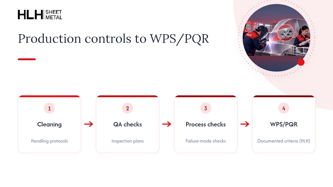
The welding workflow can include hydrogen control through quality assurance, cleaning and handling protocols, and process checks targeting common failure modes. Inspection plans get written into the WPS and PQR upfront, aligned with each client’s contract requirements before production starts, drawing on the same quality control disciplines applied across HLH’s fabrication lines. For fatigue-critical or aerospace-grade aluminum assemblies, structural welding services built around documented acceptance criteria beat chasing porosity after the fact.
FAQ
Why Do I Keep Getting Porosity In My Aluminum Welds?
Recurring porosity almost always traces back to a hydrogen source you haven’t eliminated yet: contaminated filler, a damp shielding gas line, or oxide buildup from too much delay between cleaning and welding. Start with fresh filler and a verified gas dew point before adjusting any welding parameters, since handling contamination outweighs base-metal factors in most cases.
How Much Porosity Is Acceptable In A Weld?
Acceptable porosity is defined by the governing code and the part’s service requirements, not a universal number. Project specifications built on standards like AWS D1.2 set maximum pore size and linear porosity density based on the weld’s structural or fatigue criticality, so the limit for a bracket differs from the limit for a pressure vessel.
What Causes Porosity In Aluminum?
Porosity forms because liquid aluminum dissolves far more hydrogen than solid aluminum can hold, so gas comes out of solution as the weld pool freezes. That hydrogen typically comes from moisture, hydrocarbon residue, hydrated oxide on the surface, or contaminated filler and shielding gas, according to TWI’s breakdown of aluminum porosity causes.
What Is The Porosity Of Welding?
Weld porosity refers to gas pockets trapped inside a solidified weld, ranging from microscopic pores invisible to the eye to large voids visible on radiography. In aluminum specifically, these pockets form from hydrogen that couldn’t escape the pool before the metal solidified, and their size and density determine how much they weaken the joint’s fatigue resistance.
Recommended
- 0.5–3 mm Sheet Metal: When to Specify Spot Welding for Engineers
- Spot Welding Sheet Metal: DFM Rules for China Fabrication
- Where to Get Custom Sheet Metal Welding and Assembly Services
- China Buyers: MIG vs TIG Welding Red Flags and Sample Specs

