





Table Of Contents
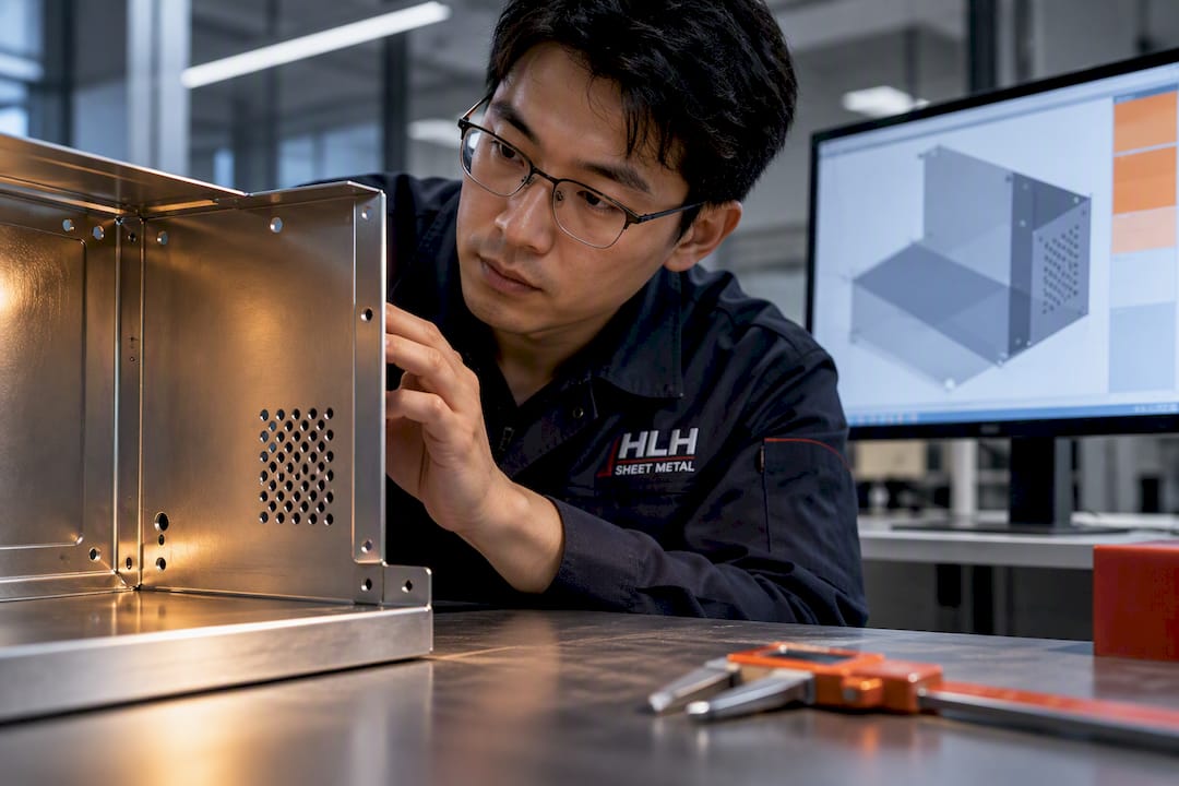
The right process for sheet metal enclosure design is to lock requirements first, choose material and thickness second, apply bending and hole DFM rules third, and validate everything with a prototype before committing to production tooling. Skip that order and you pay for it later in RFIs, tooling changes, and blown schedules. The critical checks to run early are bend radius against thickness, hole-to-bend clearance, and gasket or finish exclusion zones. Enclosure fabrication companies build enclosures following this sequence to avoid costly redesigns, which is the perspective behind everything below.
TL;DR:
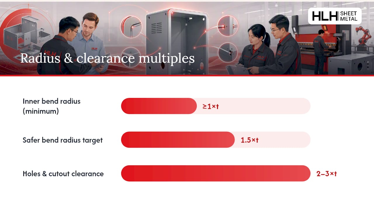
- Properly setting inner bend radius at or above material thickness, typically 1.5 times, prevents cracking and deformation during forming, especially for aluminum alloys.
- Positioning holes at least two to three times the sheet thickness away from bend lines avoids distortion and deformation during fabrication.
- Locking requirements like IP ratings, thermal dissipation needs, and service access early in design reduces costly redesigns and ensures features like gasket grooves and vent areas are correctly sized.
- Using the fabricator’s actual K-factor table for bend calculations ensures hole and cutout accuracy across multiple bends, avoiding misalignments that arise from default or generic values.
- Including layered EMI shielding features such as conductive gaskets, mesh vents limited to 20:1 aperture ratios, and ensuring metal-to-metal contact at panel joints enhances overall EMC performance.
What Requirements Drive Sheet Metal Enclosure Design?
Every dimension in your CAD model should trace back to a requirement you wrote down before you opened SolidWorks or Fusion 360. Skip this step and you end up modeling a box, then discovering three weeks later that the fan you specified doesn’t fit the vent pattern you already drew.
A CAD-first approach that validates operating environment, IP or NEMA rating, thermal budget, regulatory targets, PCB layout, and service access before modeling reduces the kind of costly redesign that shows up after tooling is cut, according to guidance from Zeta CAD Design. Lock these six inputs before you draw a single bend line:
- Operating environment: indoor/outdoor, temperature swing, humidity, dust, and chemical exposure, which determine your finish and sealing strategy.
- IP or NEMA rating target: this single number dictates gasket groove depth, cutout tolerance, and drain hole placement.
- Thermal budget in watts: how much heat the enclosure must dissipate, which sets vent area, fan count, and material choice.
- Vibration or shock class: relevant for automotive, aerospace, or industrial floor-mount equipment, and it changes fastener selection and reinforcement.
- PCB layout and connector positions: fixed early so cutouts and standoffs don’t chase a moving board revision.
- Service and access needs: whether a technician needs to swap a fan or drive, which determines panel splits and hinge or fastener choice.
Each of these maps directly to a CAD parameter. Thermal budget becomes vent area and fan cutouts. IP rating becomes gasket groove width and depth. Service access becomes where you split a lid from a chassis. Build these as named parameters in your model, not hardcoded numbers, so changing one requirement propagates through the whole design instead of forcing a manual rebuild.
Which Material And Thickness Should You Choose?
Material choice sets the ceiling on almost every downstream decision, from bend radius to EMI performance to finish cost. There’s no universal right answer here, only trade-offs that match your application.
Cold-rolled steel remains the cost-effective default with good EMI shielding, but it typically needs a corrosion-protective finish since it rusts fast when bare metal is exposed at cut edges or fastener contact points, per the same Zeta CAD Design guidance. Aluminum alloys like 5052 and 6061 run lighter and shield high-frequency EMI better, but they need thicker walls to match the stiffness of steel at the same gauge. 304 and 316 stainless cost more and form less easily, but they hold up in washdown or coastal environments where corrosion is the primary failure mode.
Typical thickness ranges by application:
- Light instrument housings and consumer-facing panels: 0.8 to 1.2 mm
- General industrial enclosures and server chassis: 1.2 to 2.0 mm
- Structural or floor-mounted equipment housings: 2.0 to 3.0 mm
Statistic Callout: Powder coat commonly adds a measurable thickness per surface, which must be accounted for in your tolerance stack on any feature with a tight-fit requirement, according to PCBWay’s fabrication guidance.
K-factor is the variable that determines how your flat pattern unfolds from your 3D bent model, and getting it wrong throws off every hole and cutout position after the bend. Most CAD packages default to a generic K-factor value that doesn’t match your specific material and thickness combination, so pull the real value from your fabricator’s bend tables rather than trusting the software default. Model anodize as strictly non-conductive in your finish layer too, since it will block grounding continuity anywhere it’s applied over a contact surface.
How Do Bend Radius And Bend Reliefs Affect The Design?
Bending is where most first-pass enclosure designs fail, and almost all of the failures trace back to a handful of rules engineers know but forget to enforce in CAD.
- Set inner bend radius at or above material thickness. The floor is r ≥ t, but 1.5×t is the safer target across most alloys, and PCBWay’s design guide confirms this as the standard heuristic. Aluminum in particular wants a more generous radius than steel at the same thickness, since it cracks sooner along a tight bend line.
- Add bend relief cuts wherever a bend line meets a cutout edge. Without relief, the sheet tears at the bend’s terminus instead of folding cleanly.
- Keep holes and cutouts at least 2 to 3 times material thickness away from any bend line. This clearance rule, also confirmed in the PCBWay guide, keeps features from deforming when the press brake forms the bend.
- Set flange heights with clearance for the tooling, not just the finished part. A flange too short for the press brake’s die opening will show visible marking or won’t form at all.
- Sequence your bends to minimize opposing folds on the same operation. Splitting a complex part into two forming operations is often cheaper than fighting a single setup that requires the sheet to flip mid-process.
K-factor errors compound across every bend in a multi-fold part, so a part with six bends and a wrong K-factor value can drift several millimeters off target by the final flange.
Pro Tip: Pull your fabricator’s actual K-factor table for your specific material and thickness before finalizing flat patterns. A generic software default can throw off hole alignment on parts with more than two or three bends, and you won’t catch it until the first article comes back wrong.
For a deeper walkthrough of these DFM defaults inside your CAD tool, HLH SHEET METAL’s practical design guide for engineers breaks down the settings that matter most before you release a drawing.
What Hole And Cutout Tolerances Should You Design To?
Fit problems on the bench almost always trace back to a tolerance nobody called out on the drawing. Laser cutting and punching typically hold tolerances around ±0.1 to 0.3 mm, and bending angle tolerance runs near ±0.5 degrees, figures confirmed by PCBWay’s design reference. Neither number is optional in an assembly with mating panels or PCB standoffs.
- Never spec a hole smaller than material thickness. Below that, the punch or laser struggles to hold a clean edge, and the hole distorts.
- Keep hole-to-edge distance at 2 times thickness minimum. Closer than that and the edge deforms during cutting or bending.
- Design slots, not round holes, wherever thermal expansion or stack tolerance is a factor. A slot absorbs variance that a round hole can’t.
- Check PEM insertion clearance against the fastener manufacturer’s spec sheet. PEM nuts and studs need a specific hole diameter and minimum sheet thickness to seat and hold torque correctly.
Before you release any drawing, run this compact checklist: confirm connector footprints use the actual manufacturer’s CAD model rather than a placeholder block, recheck every hole-to-bend distance against the 2 to 3×t rule, verify lid and panel gaps are uniform around the full perimeter, and flag every finish exclusion zone directly on the model, not just in a drawing note. A DFM checklist covering bend reliefs, K-factor settings, and clearance verification is what separates designs that build clean from ones that bounce back for rework.
How Do You Model Vents And EMI Shielding In CAD?
Thermal and EMI requirements often pull in opposite directions. More vent area cools better; more vent area also leaks more EMI. Solving that tension happens in CAD, not on the bench after the fact.
Position intake vents near your hottest components and place exhaust above them, letting convection do part of the work instead of relying purely on forced air, a principle laid out in PCBWay’s thermal guidance. Model fan cutouts to the fan’s actual bolt-circle dimensions rather than an approximate hole, and add clearance for the fan guard’s stack height so the finished assembly doesn’t interfere with a neighboring panel.
Statistic Callout: The 20:1 aperture rule caps any EMI-relevant opening at less than one twentieth of the wavelength at your highest frequency of concern. At 1 GHz, that limits the longest dimension of any vent aperture to roughly 15 mm, per Zeta CAD Design’s EMI guidance.
That rule usually forces a honeycomb vent panel or a perforated grille with small individual openings instead of one large cutout, since a single 60 mm vent hole leaks EMI far worse than a grid of 10 mm holes covering the same open area.
- Model gasket grooves to the gasket manufacturer’s recommended compression ratio, typically 20 to 30 percent, since under-compression leaks and over-compression cracks the gasket over time.
- Flag finish exclusion zones on every EMI contact surface, since powder coat or anodize breaks conductivity exactly where you need metal-to-metal contact.
- Treat grounding as a modeled feature, not an afterthought: place a dedicated grounding stud location on the chassis and confirm metal-to-metal contact at every panel joint rather than leaving continuity to whatever wire a technician adds later.
What Assembly And Fastening Method Fits Your Design?
Volume and serviceability decide this more than anything else. High-volume consumer enclosures lean on welds and PEM fasteners for speed and a clean finished look. Low-volume or field-serviceable industrial gear leans on screws and rivets because they’re faster to rework and don’t require a welding fixture.
- Welding and spot welding: strongest joint, cleanest finish, but requires edge prep and post-weld grinding, and it’s expensive to modify once built.
- Rivets: fast, cheap, and don’t require a threaded feature, but they’re permanent and show on the surface.
- PEM fasteners: give you a threaded insert in thin sheet metal, ideal for field-removable panels, but they need precise hole diameter and minimum edge distance to install without pulling out.
- Screws into tapped bosses or standoffs: best for anything a technician needs to open repeatedly, but they add a boss geometry requirement to your model.
Whatever method you choose, model the access clearance for the installation tool, not just the fastener itself. A rivet gun or torque driver needs swing room that a bare 3D model often ignores.
Design for manufacturing best practices favor reducing part count through bent tabs and formed features instead of welding two flat pieces together, since fewer welds mean fewer opportunities for warpage, according to Zeta CAD Design’s assembly guidance. Unify fastener types across the whole enclosure where possible. A single screw size across the entire assembly speeds up both fabrication and field service.
How Many Prototypes Do You Need Before Production?
Most enclosure programs need somewhere between one and three production-representative prototypes before tooling gets cut for volume runs. Fewer than that and you’re gambling on a design that’s only been checked on screen.
- Build the first prototype from the exact production material and thickness, not a stand-in, so bend behavior and springback match what you’ll see at scale.
- Run dimensional fit checks first, confirming panel gaps, connector alignment, and PCB standoff positions match the CAD model within tolerance.
- Test gasket compression and EMI continuity together, since a gasket groove that looks correct on screen can still under-compress once real tolerance stack-up is in play.
- Run vibration, drop, and IP sealing tests appropriate to your application’s duty cycle, and record every failure directly against the parametric feature that caused it so the fix propagates automatically through the model.
- Set a clear pass criterion before you start, typically zero critical dimensional failures and a sealed IP test result, before authorizing production tooling.
HLH SHEET METAL’s rapid prototyping process is built around exactly this kind of production-true validation, catching springback and fit issues before they become a tooling bill.
How Does HLH SHEET METAL Support Enclosure Fabrication?
Some enclosure and chassis fabricators operate through ISO-certified quality control with rapid prototyping and multiple manufacturing plants capable of handling both single proof-of-concept units and large production runs without vendor switches. English-speaking support teams can handle technical questions directly, which matters for fast clarification of tolerance callouts or finish specs.
To get an accurate quote and cut down on RFIs, send a fabricator a complete package: STEP or Parasolid CAD files, a drawing calling out critical dimensions and tolerance zones, the material and finish specification, and any gasket or finish exclusion zones marked explicitly. Skipping any one of these is the single most common reason a quote comes back with clarifying questions instead of a price.
How Do You Control Deformation And Springback?
Springback happens because sheet metal doesn’t bend perfectly plastically. Some elastic recovery occurs the moment the press brake releases the part, and the bend angle opens back up slightly from whatever angle the tooling formed. Ignore this and every bent flange comes out a degree or two off from the model.
The fix starts with your K-factor value, since an accurate K-factor already accounts for a material’s typical springback behavior at a given thickness and bend radius. Beyond that, thicker material and higher-strength alloys spring back more than thin, soft material, so a 6061-T6 aluminum panel needs a more aggressive overbend allowance than a mild cold-rolled steel panel at the same thickness.
Talk to your fabricator about their standard overbend compensation for your specific material and press brake tooling rather than assuming a universal correction factor works everywhere. Shops that run the same alloy and gauge repeatedly usually have empirical compensation values dialed in from actual production data, and those numbers beat a generic textbook K-factor every time.
Deformation issues also show up away from the bend line, particularly in large flat panels that oil-can or bow after cutting relieves internal stress in the sheet. Adding a shallow rib or emboss across a large flat panel adds stiffness without adding thickness, and it’s cheaper than upgrading the whole panel to a heavier gauge just to stop it from flexing. Validate any panel prone to this on your first prototype run rather than assuming the CAD model’s flat, stress-free geometry will match the real formed part.
How Do You Layer Shielding Into An Enclosure Design?
EMI shielding works best as a layered system rather than a single material choice. The enclosure’s base metal handles the bulk of the shielding job, but every seam, vent, and cable penetration is a potential leak point that the base material alone can’t close.
Start with continuous metal-to-metal contact at every panel joint, since a gap of even a fraction of a millimeter at a seam can leak more EMI than a properly designed vent aperture. Conductive gasket material, often a metal mesh or conductive elastomer, fills seams that can’t achieve direct metal contact, particularly around removable access panels. Where cables pass through the enclosure wall, a shielded connector with a 360 degree conductive backshell keeps the cable’s own shielding continuous with the chassis rather than creating a gap at the penetration point.
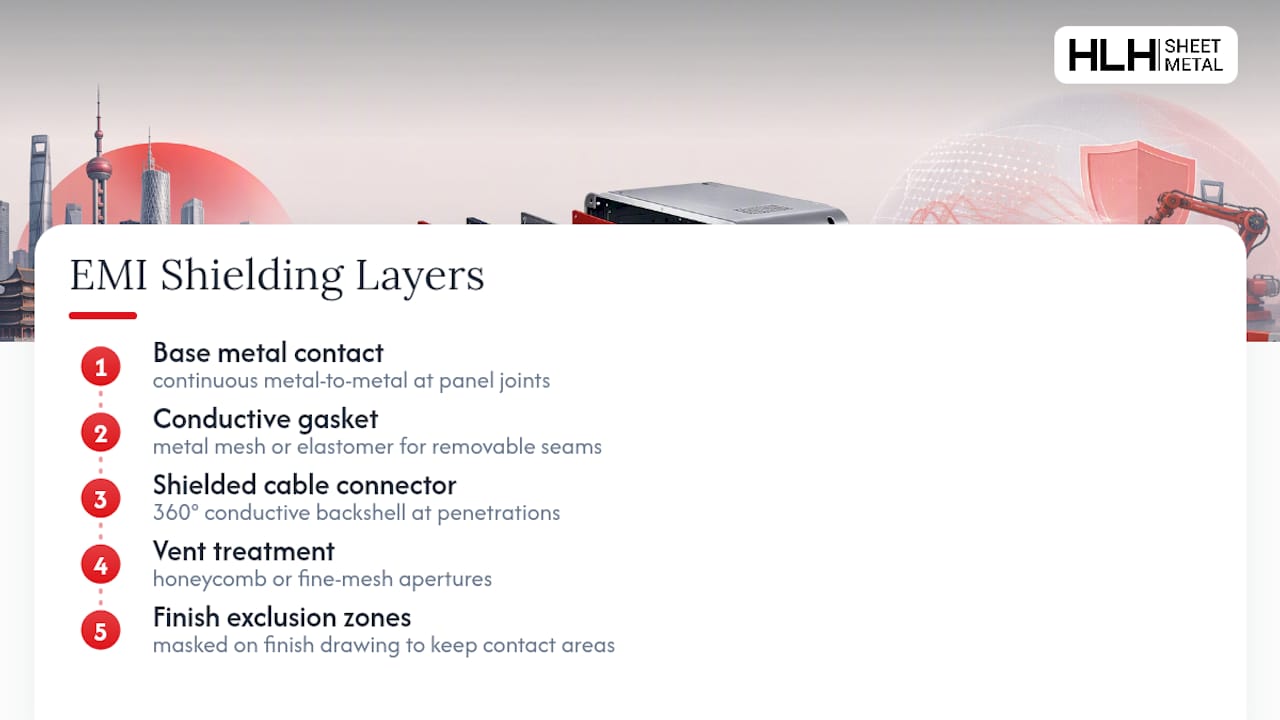
Vent apertures need the honeycomb or fine-mesh treatment discussed earlier, and any window or display cutout needs a transparent conductive film or fine wire mesh if EMI containment matters at that frequency range. Layer these together and you get a system where no single point is the weak link. Skip any one layer, and that becomes the leak path a compliance test will find.
Finish selection matters here too. Powder coat and anodize both insulate, so any surface intended as an EMI contact point needs a masked exclusion zone during finishing, called out explicitly on the finish drawing rather than left to the finishing shop’s judgment.
What Corrosion And Sealing Factors Go Beyond Material Choice?
Material selection sets a corrosion baseline, but the actual seal design and coating system decide whether an enclosure survives its rated environment for years or fails in months. Two enclosures built from identical stainless steel can perform completely differently in the field if one has a properly compressed gasket and the other doesn’t.
Gasket compression ratio is the detail most designs get wrong. A gasket compressed to the manufacturer’s recommended 20 to 30 percent range seals reliably across temperature cycling, while an under-compressed gasket leaks and an over-compressed one takes a permanent set and stops sealing after a few thermal cycles. Drain holes matter just as much in outdoor or washdown applications, positioned at the lowest point of any internal cavity so condensation or wash water has somewhere to go instead of pooling against a seam.
Coating choice interacts directly with the sealing strategy. A powder coat finish protects flat surfaces well but can chip at fastener contact points and cut edges, exposing bare metal exactly where moisture collects. Anodize on aluminum resists corrosion without adding meaningful thickness, but it can’t be relied on for EMI contact, which is why those zones need masking during the anodizing process. For enclosures destined for marine or coastal environments, the finishing approach used in marine aluminum fabrication offers a useful reference point, since saltwater exposure punishes any coating gap far faster than a typical indoor industrial setting.
Fastener material matters too. Mixing a stainless fastener into a bare aluminum panel sets up galvanic corrosion at every contact point unless you isolate them with a washer or coating, a detail that’s easy to miss until field returns start coming back with white corrosion powder around every screw head.
How Do You Design For Easy Assembly And Maintenance?
An enclosure that’s cheap to build but painful to service costs more over its lifetime than one designed with maintenance in mind from the start. This matters most for equipment that lives in the field for years, where a technician might need to swap a fan, a power supply, or a board without disassembling the entire chassis.
Access panels are the simplest lever here. Splitting a lid into a full-cover panel plus a smaller service door over just the components that fail most often, a fan or a fuse, lets a technician do routine maintenance without exposing the whole interior to dust or handling risk. Hinge the larger panels where possible rather than requiring full removal, since a hinged door speeds up routine service and reduces the chance of a technician losing a fastener in the field.
Modularity pays off on any product built in multiple configurations. A chassis designed with a common base and interchangeable front or rear panels lets you support several product variants without redesigning the whole enclosure for each one. This also simplifies spare parts inventory, since a distributor can stock one base chassis and a handful of panel variants instead of several complete, non-interchangeable enclosures.
Fastener choice ties back into serviceability directly. A captive screw that stays attached to the access panel beats a loose screw that a technician can drop into the equipment during a repair, particularly in dusty or elevated installation environments where a dropped fastener is genuinely hard to recover.
Author’s Practical Takeaways From Enclosure Manufacturing
Three lessons keep surfacing across enclosure projects. First, plan gasket grooves before you finalize panel thickness, not after, since retrofitting a groove into an already-toleranced panel usually means starting the flat pattern over. Second, lock connector positions early. A late connector swap almost always cascades into a cutout change, a bend relief change, and a re-check of every hole-to-bend distance around it. Third, build fixes into parametric features rather than one-off edits, so a single dimension change propagates cleanly instead of requiring you to hunt down every downstream reference by hand.
One habit that consistently prevents rework: modeling gasket compression as a driven dimension tied to groove depth, so changing gasket vendors doesn’t mean redrawing the whole seal path. For projects that need a fast prototype-to-production handoff, a fabrication partner like HLH SHEET METAL can shorten that loop considerably.
— Nash
Ready To Move From CAD Model To Fabricated Enclosure?
Some fabrication companies turn a finished enclosure design into a physical part aiming to reduce the back-and-forth common in overseas fabrication relationships. Features such as ISO-certified quality control, rapid prototyping, and multiple manufacturing plants can enable the same partner to handle both initial proof-of-concept units and full production volumes, supported by English-speaking teams for timely technical assistance.
The services that matter most for enclosure work are all covered under one roof: sheet metal fabrication, laser cutting for tight-tolerance cutouts, bending services for accurate flange geometry, welding for structural joints, and surface finishing for powder coat or anodize with properly masked exclusion zones. For enclosures with power distribution or disconnect requirements specifically, the custom disconnect enclosure manufacturing service is built around exactly that use case.
To get a fast, accurate quote, send over your STEP or Parasolid file, a drawing calling out critical dimensions and tolerance zones, your material and finish spec, and any assembly notes on gasket compression or fastener type. That package is what lets a fabricator quote in days instead of going back and forth on missing details. Start by requesting a quote through the sheet metal fabrication capabilities page.
FAQ
What Are The Key Design Considerations For Sheet Metal Enclosure Design?
The main considerations are operating environment, IP or NEMA rating, thermal budget, PCB layout, and service access, all defined before modeling starts. Material choice, bend radius, hole-to-bend clearance, and finish exclusion zones for EMI contact follow directly from those requirements.
What Are Common Sheet Metal Design Mistakes?
The most frequent mistakes are setting bend radius below material thickness, placing holes too close to a bend line, and forgetting to mask finish exclusion zones on EMI contact surfaces. Ignoring K-factor and springback compensation also causes flat patterns to come out misaligned after bending.
What Are The Basic Design Guidelines For Sheet Metal?
Keep inner bend radius at or above material thickness, with 1.5 times thickness preferred, and hold hole-to-bend distance at 2 to 3 times thickness, per PCBWay’s design guidance. Account for laser and punch tolerances around ±0.1 to 0.3 mm and bending tolerance near ±0.5 degrees when stacking dimensions.
Do Metal Enclosures Need To Be Grounded?
Yes, most enclosures housing electronics need continuous grounding to control EMI and meet safety requirements. Design a dedicated grounding stud location and ensure metal-to-metal contact at panel joints rather than relying on wiring added after fabrication, following the grounding approach described by Zeta CAD Design.
How Much Does Custom Enclosure Fabrication Cost?
Cost depends on material, thickness, finish, and production volume, so there’s no single flat rate across projects. Current pricing for HLH SHEET METAL’s fabrication services is available by requesting a quote with your CAD files and specifications.
Recommended
- Sheet Metal DFM: A Practical Design Guide for Engineers
- Sheet Metal Prototyping: A Rapid, Production-True Guide
- Sheet Metal DFM: CAD Settings That Cut China Production Costs
- Design Enclosures to 19-Inch Rack Standards for China

