




Table Of Contents
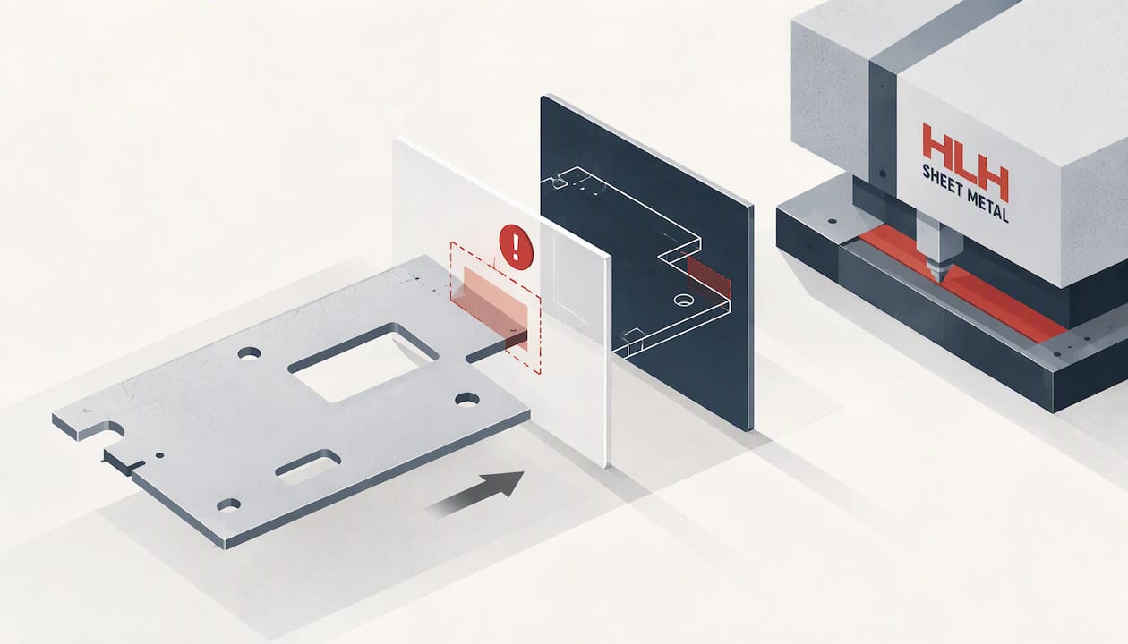
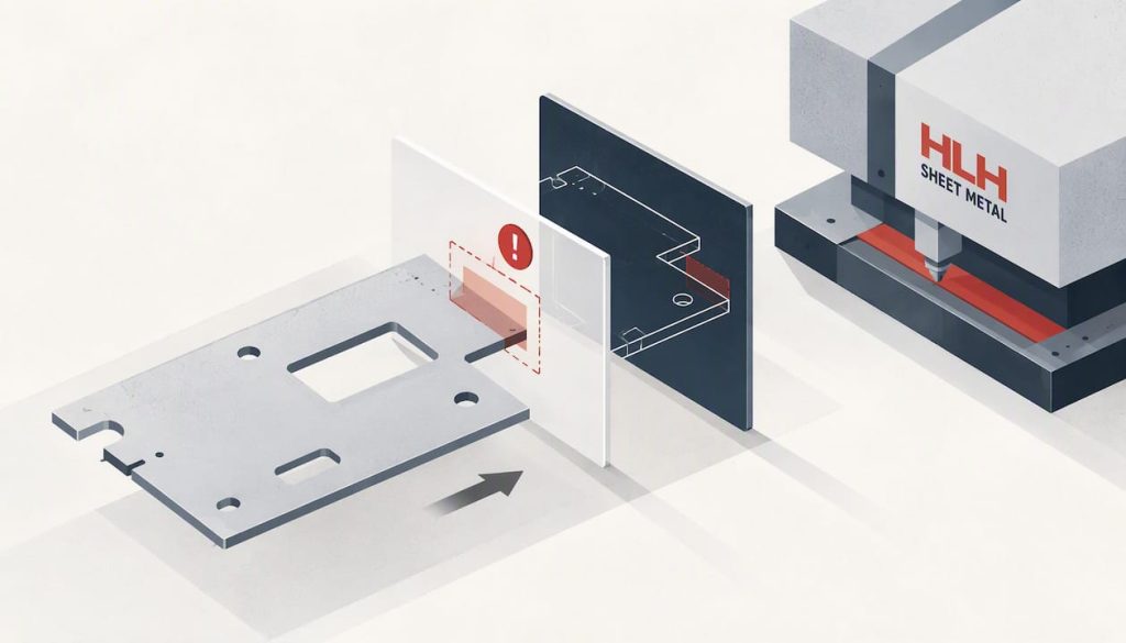
We deliver sheet metal fabrication with design assistance included. Our engineers review your CAD for manufacturability, flag costly features before cutting starts, and then build the prototypes and production runs, which shortens the loop between revision and finished part. ISO-backed quality assurance keeps risk low. Start with our fabrication capabilities page and upload your files.
TL;DR:
- Keep the inside bend radius close to sheet thickness, place holes two to three thicknesses from bends, and reserve tight tolerances for functional surfaces.
- Send a STEP model, plus any DXF flat patterns, and specify material, thickness, finish, quantity, critical tolerances, and delivery date to prevent quote assumptions.
- Simple laser cut and bent prototypes can ship in days, with some digital operations reaching one to two days; production usually takes weeks.
- Laser cutting avoids hard tooling costs for low and mid volumes, while stamping dies raise upfront expense but can lower unit prices as quantities grow.
- For projects with repeated revisions, favor shops that keep cutting, bending, welding, and finishing in house; subcontracted steps add transit and handoffs.
What Do Fabricators With Design Assistance Actually Offer?
When a supplier bundles design support with fabrication, you are buying two things at once: a manufacturing line and an engineering second opinion. The second opinion is the part that saves money, because a drawing that looks fine in CAD can hide a bend that tears, a hole that distorts, or a flange that cannot be formed on standard tooling.
Core Processes You Should Expect
A capable shop covers the full forming chain under one roof:
- Laser cutting for flat blanks, intricate cutouts and tight nesting on sheet and plate.
- Punching for repeated holes, louvers and extruded features at higher volumes.
- Bending and forming on press brakes, including multi-bend parts and channels.
- Stamping for runs where progressive or single-stage dies pay back the tooling.
- Welding and assembly, from spot and TIG welds to hardware insertion and sub-assemblies.
You can see each process on its own page: laser cutting, bending, stamping and welding.
Finishing And Secondary Services
Parts rarely leave the press brake ready to ship. Typical secondary work includes powder coating, anodizing on aluminum, plating, passivation on stainless, deburring and final assembly. Finish choice affects design more than most engineers expect. A powder-coated part gains thickness on every surface, so tight-fit tabs and slots need clearance. Specialist coaters publish detailed work for demanding environments; one example is this marine fabricated components case study, which shows how large, complex metal parts are prepared and coated. Our surface finishing services cover the finishes most product teams request.
Materials And Thickness
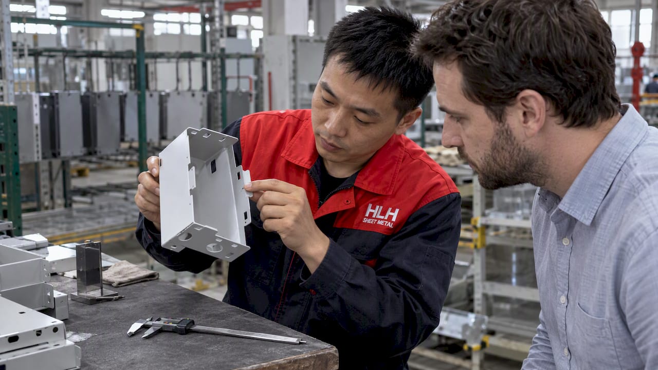
We work with steel, stainless steel, aluminum, galvanized steel, copper, brass, titanium and magnesium. For prototypes, teams often pick the production material from the start so that bend behavior, springback and finish response match what ships later. Thin gauges suit enclosures and brackets, while heavier plate suits structural frames. Springback differs between aluminum and stainless, so a part that bends cleanly in one can need a different bend allowance in the other.
How Capability Limits And DFM Feedback Are Presented
Reputable fabricators state their limits plainly: maximum and minimum thickness per material, achievable tolerances, and the largest sheet or nest size their machines accept. Ask for these before you design, not after you receive a quote.
DFM feedback usually arrives in one or more of these forms:
- Marked-up CAD or PDF drawings with the problem features circled.
- 3D visualizations showing where a bend collides with a flange or tool.
- Written engineering comments proposing a specific change, such as moving a hole or adding a relief.
Information-rich 3D CAD has become the standard way to communicate these details precisely, and it speeds up feedback, as The Fabricator reports on precision sheet metal software.
In-house Versus Subcontracted Prototyping
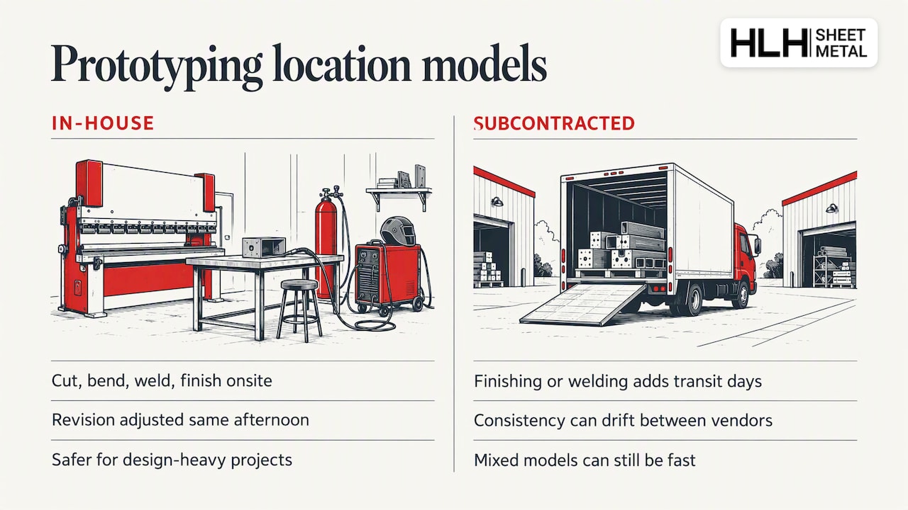
Where the work is done changes your schedule. A shop that cuts, bends, welds and finishes in one building can adjust a part the same afternoon you approve a revision. A shop that subcontracts finishing or welding adds transit days and handoffs, and part-to-part consistency can drift between vendors. Subcontracting is not automatically bad: mixed in-house and outsourced models can still deliver very short lead times when quoting is digital. For design-heavy projects with several revisions, in-house control is the safer bet.
Which DFM Rules Will A Supplier Apply To Your Design?
Design assistance is only useful if you understand what it checks. The rules below are the ones our engineers apply first. They follow the standard guidance published in the Engineering LibreTexts DFM guidelines, and our own sheet metal DFM guide for engineers goes deeper on each one.
The Checklist
- Keep one bend radius, roughly equal to sheet thickness. A 2 mm radius on 2 mm steel forms cleanly, while a 0.5 mm radius on the same sheet risks tearing. A single radius also means one tool setup instead of several.
- Keep holes and cutouts sufficiently far from bend lines to avoid distortion. Closer features stretch into ovals when the metal flows around the bend.
- Make flanges long enough to maintain structural integrity. Shorter flanges cannot be gripped by the die and lose structural strength.
- Add relief notches where bends meet. Without them, the material tears at the intersection corner.
- Design for standard punch and die sizes. Odd hole diameters or unusual slot shapes force custom tooling, and that cost lands on your quote.
Good versus risky in practice: imagine an aluminum bracket. A suitable inside radius, holes placed well away from the bend and a sufficiently long flange can help it form cleanly. A tight radius, a hole close to the bend and a short flange can invite cracking, distorted holes and a part that slips in the die. Both versions look similar on screen, which is exactly why a manufacturability review matters.
Tolerances: Call Out Only What Matters
Standard bend and cut tolerances are achievable at standard prices. Tighten a tolerance only where function demands it, such as a mating surface, a bearing seat or a sealing edge. Blanket tight tolerances across a whole drawing raise inspection time and scrap rates without improving the product. Mark critical dimensions clearly and let everything else default to the shop standard, then confirm that standard with your supplier in writing.
Preparing CAD So Feedback Is Actionable
Good input produces good feedback. Before you upload:
- Export the native 3D model as STEP, and add DXF flat patterns if you already have them.
- Annotate material, thickness, finish and quantity on the drawing.
- Include assembly or exploded views for multi-part products so the reviewer sees how parts mate.
- Mark hardware callouts (inserts, studs, nuts) with part numbers or sizes.
- Note any cosmetic faces so the shop protects them during handling.
Digital workflows have shortened review cycles considerably. As The Fabricator describes, one- or two-day lead times are not unusual for certain prototype or small-lot operations, and clean CAD is what makes that pace possible. Messy files cost days in back-and-forth.
How Do Quoting, Lead Times And Prototyping Work When Design Help Is Included?
Adding a manufacturability review to your request for quote adds a step, but it removes larger delays later. Here is the typical cadence.
The Quoting Sequence
- Submit your files. Upload CAD, quantities, material, finish and tolerance notes through the quote form.
- Receive the DFM review. An engineer checks bends, hole positions, flanges, reliefs and tooling fit, then sends comments or markups.
- Revise and confirm. You accept the changes or explain why a feature must stay. Complex parts may go through multiple review cycles.
- Receive the final quote. Pricing reflects the confirmed design, so it does not change after cutting begins.
- Build the prototype. Approval triggers cutting, forming, welding and finishing.
- Scale to production. Once the prototype passes, volume orders use the same validated process.
Lead Times
Lead time depends on process mix and queue. Rapid prototypes of simple laser-cut and bent parts can ship in days, and some digitized operations reach one to two days. Standard production runs normally take weeks, because they involve material procurement, longer machine time, finishing batches and inspection. Several things shorten the window: simple geometry, common materials, standard finishes and prompt approvals from your side. Several things lengthen it: exotic alloys, multi-stage finishing, hardware sourcing, and slow answers to engineering questions. Our sheet metal prototyping guide walks through how to keep prototype loops short.
What Drives Per-unit Price
Volume is the biggest lever. Laser cutting needs no hard tooling, so it suits low and mid volumes with little upfront cost. Stamping dies cost more at the start but lower the unit price sharply once quantities climb. Finish choices also move cost: powder coat and anodizing are priced per batch and per surface area, and extra masking adds labor. Material and thickness set the base cost, and tight tolerances add inspection time.
Documentation That Produces Accurate Quotes
Give the estimator the full picture on the first submission: CAD files, required quantities (including expected annual volume), material and grade, finish specification, critical tolerances, and delivery date. Missing details force assumptions, and assumptions become price changes later.
Requesting Expedited Prototyping
If the schedule is tight, say so in the request. Expedited work usually means priority machine time and a compressed finishing window, and the trade-off is a higher price. You can often reduce that premium by simplifying the finish, using a stocked material, or approving the DFM comments quickly.
How Do You Choose A Fabricator That Adds Real Value?
Not every shop that advertises design help delivers it. Use a short, repeatable process to compare candidates.
What To Evaluate
- Design support process: who reviews your files, how fast, and in what format.
- Material and process fit: does the shop run your alloy and forming method in-house?
- Prototyping speed: realistic days to first parts, not best-case marketing.
- Certifications: ISO or industry standards relevant to your sector.
- Communication: response time, named contacts, and language support if you work across time zones.
Questions Worth Asking
- How many business hours does engineering feedback usually take?
- Can you share a sample DFM report from a similar part?
- Which inspection methods and equipment do you use, and what documents ship with parts?
- What is your current capacity, and how do you handle a rush order?
- Which steps are subcontracted?
Trust Signals To Request
Ask for current ISO certificates, sample inspection data, and references from customers in comparable industries such as aerospace, medical or industrial equipment. A shop that hesitates to share these is telling you something.
A Simple Scoring Approach
Rate each supplier from 1 to 5 on design support, process fit, speed, quality evidence and communication. Weight the categories to match your project: a medical device team might double the weight on quality evidence, while a startup racing to launch might double speed. Multiply, add up, and the ranking becomes obvious. Run it on three suppliers and the decision rarely needs more than a day.
Why Integrated Design Review And Fabrication Wins
Most hidden cost in custom metal parts comes from the gaps between design and manufacturing: a revision that waits for an email, a bend that fails on the floor, a quote that changes after the first article. When the engineer who reviews your drawing works in the same facility as the press brake, those gaps shrink. Teams that get the most from this arrangement share files early, accept rule-based changes quickly, and reserve tight tolerances for features that truly need them. In my view, a supplier’s DFM comments are a cost-effective form of quality control, and the best time to use them is before the first sheet is cut.
— Nash
How Do We Support Engineers Who Need Design Help And Fabrication Together?
We combine design-for-manufacturability review, rapid prototyping and production under one roof, so your revision loop stays short and your quote reflects the real part. Our teams respond in English around the clock for international projects. What backs that up:
- ISO-certified quality assurance across our processes.
- Multiple manufacturing plants in China, which let us turn prototypes quickly and scale to larger runs.
Upload your CAD or request a quote on our sheet metal fabrication page and our engineers will come back with manufacturability comments and pricing.
FAQ
What Is The Difference Between A Sheet Metal Worker And A Fabricator?
A sheet metal worker typically cuts, forms and installs thin metal, often in construction and ductwork. A fabricator builds finished parts and assemblies in a shop, using cutting, bending, welding and finishing processes, usually from engineering drawings.
What Services Does Metal Fabrication Include?
Metal fabrication covers cutting, punching, bending, stamping, welding, assembly and surface finishing such as powder coating, plating or anodizing. Many shops also provide prototyping and design review so parts are easier to build.
How Long Does A Sheet Metal Prototype Take?
Simple prototypes can ship in days, and digitized operations sometimes manage one to two days, as The Fabricator notes. Production runs usually take weeks, depending on material, finish and volume.
How Do I Get The Most Accurate Quote?
Send 3D CAD, a drawing with critical tolerances, material and thickness, finish, quantities and a target delivery date. Complete files let engineers apply manufacturability rules up front, so the price holds after review.
Do I Need To Follow Bend Radius Rules?
Yes. A bend radius close to the sheet thickness is the standard recommendation, and features placed 2–3 times the thickness from bends stay true, according to the Engineering LibreTexts DFM guidelines.

