





Table Of Contents

The 19-inch rack standard fixes a mounting width of 482.6 mm (19 in) and a rack unit of exactly 1.75 in (44.45 mm), with a repeating vertical hole pattern of 0.5 in, 0.625 in, and 0.625 in center-to-center spacing. Rail centers sit roughly 465.1 mm (18.312 in) apart. The two documents that govern all of this are EIA-310 and IEC 60297-3-100, and everything else, from cabinet depth to door style, is a manufacturer’s choice.
TL;DR:
- Most hardware from different vendors can fit together in a 19-inch rack if the mounting holes follow the standardized pattern, especially Type II grids.
- Proper measurement of equipment width, rail spacing, and device depth is crucial to prevent fitment issues during installation.
- Maximum usable rail gap is approximately 450.85 mm, with wider external cabinets (600 mm or 800 mm) recommended for cable management and airflow.
- Custom racks should specify tight hole tolerances, correct thread types (preferably M6), and precise fabrication details to avoid rework and fitting problems.
- Grounding and cable management must adhere to strict standards to ensure safety, reliable operation, and easy maintenance.
Why Do 19-inch Rack Standards Exist?
The 19-inch mounting format didn’t originate in IT. It came out of early 20th-century telephone switching equipment, where operators needed racks of relay panels that could be swapped between central offices without redesigning every frame. By the time computing and telecommunications converged in the late 20th century, the format had already proven itself across decades of equipment turnover, and the EIA formalized it as EIA-310, with the IEC later publishing the international equivalent.
The standard survives because it locks down only the interface, not the enclosure. That’s a deliberate design choice, and it’s why a server built in 2026 still bolts into a frame designed decades ago.
What the standard fixes:
- Mounting width (482.6 mm / 19 in)
- Rack unit height (1U = 1.75 in / 44.45 mm)
- Vertical hole spacing and repeat pattern
What it leaves open:
- Cabinet depth and external width
- Door style, side panel design, and cable routing
- Load rating and structural bracing
That split matters more than most procurement teams realize. Multi-vendor interoperability doesn’t depend on every manufacturer agreeing on aesthetics or depth. It depends on everyone agreeing on where the holes go, and that narrow agreement is what makes it possible to mix a switch from one vendor with a PDU from another in the same frame.
What Are The Core Mechanical Specifications?
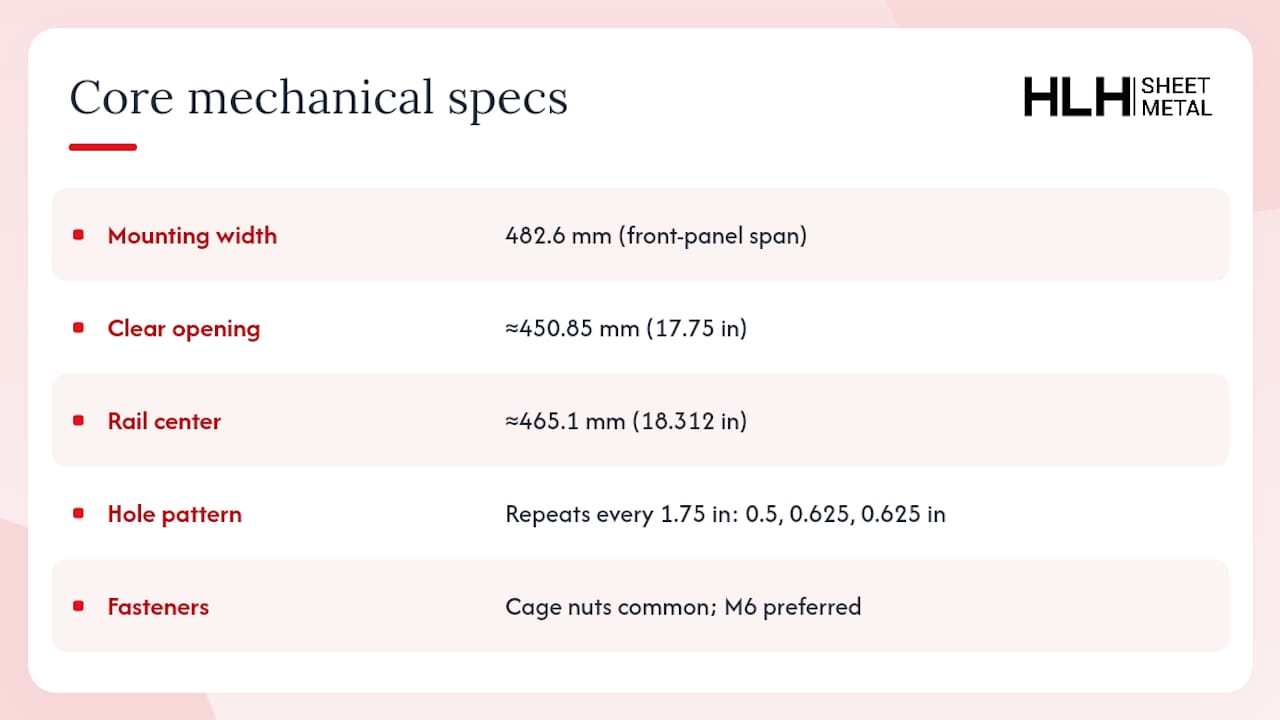
The mounting width of 482.6 mm defines the front-panel span, not the cabinet’s outer shell. Because the mounting rails themselves take up material, the usable gap between rails, the actual clear opening equipment slides into, comes out to roughly 450.85 mm (17.75 in). That distinction trips up a surprising number of first-time buyers who assume “19 inch” describes the whole cabinet.
Rail center-to-center distance runs approximately 465.1 mm (18.312 in), a figure that shows up on nearly every EIA-compliant rail drawing. Manufacturers typically hold this dimension to a tight tolerance because even small deviations compound across a 42U or 48U frame, throwing off alignment for blind-mate connectors and sliding rail kits.
The vertical hole pattern is where most fitment confusion starts. Rather than uniform spacing, holes follow a repeating three-hole group: 0.5 in, then 0.625 in, then another 0.625 in, and the whole group repeats every 1.75 in, which is exactly one rack unit. Get this pattern wrong on a custom rail and every piece of gear above the error will sit slightly off.
Pro Tip: If you’re designing a custom rail plate, cut the three-hole group first and verify it against a physical 1U spacer before drilling the full column. A 1 mm error at the top of a repeating pattern becomes several millimeters of misalignment by the time you reach 42U.
On fasteners, IEC 60297-3-100 specifies two mounting grid types: Type I, which matches basic front-panel holes, and Type II, which adds universal holes for broader hardware compatibility. Cage nuts remain the most common fastening method in field-installed racks because they let you swap thread sizes without re-tapping the rail, while the standard’s preferred thread is M6, chosen specifically to support interoperability across vendors. Older American equipment sometimes still specifies #12-24 screws, which fit the same hole pattern but use a different thread pitch, so check your hardware kit before assuming compatibility.
How Do Common Cabinet Sizes Compare?
Once you’re past the mounting grid, the next decision is picking a cabinet envelope that fits your equipment load and your floor space. U count drives mounting height directly since every U adds exactly 44.45 mm, but external width and depth are where real-world choices diverge.
External cabinet widths cluster around 600 mm and 800 mm, with 600 mm often chosen to match raised-floor tile dimensions in legacy data centers. Depth is the dimension nobody standardized, and it commonly ranges from about 600 mm up to 1,200 mm or more, driven entirely by how deep your servers, switches, and cable management arms actually are.
What Mounting Hardware And Hole Types Should You Use?
Rail hole geometry and fastener choice determine whether your equipment goes in smoothly or fights you at every screw. Type II mounting grids, which add extra universal holes beyond the basic Type I pattern, give you more flexibility when mixing gear from different manufacturers on the same rail, and they’re worth specifying whenever you expect the rack’s contents to change over its service life.
Cage nuts stay the default choice for field-serviceable racks because they let a technician swap between M6, M5, and #10-32 threads without re-machining anything. Fixed threaded rails, where the thread is tapped directly into the rail, offer more rigidity for permanent installations but cost more to correct if you specify the wrong thread size upfront.
Rail thickness isn’t cosmetic. Thicker steel rails hold tolerance better under repeated insertion and removal, but they also eat into that 450.85 mm usable gap, so a rail that’s slightly overbuilt can create real clearance problems for wide equipment.
Key hardware considerations:
- Prefer M6 threads for new installations; it’s the thread IEC 60297-3-100 recommends for cross-vendor compatibility.
- Use cage nuts when the rack will see frequent equipment changes over its lifespan.
- Add horizontal shelf brackets for any device heavier than what its front-panel ears alone can support.
- Check rail gauge against your heaviest planned device before final fabrication.
Pro Tip: For racks that will house a mix of legacy and modern equipment, spec Type II universal hole grids from the start. Retrofitting extra holes into an installed rail is far more expensive than including them during fabrication.
How Do You Verify Equipment Compatibility Before Ordering?
Fitment failures almost always trace back to a measurement nobody checked before the equipment shipped. A short verification pass before procurement catches nearly all of them.
- Measure the equipment’s overall front-panel width, including the mounting ears, and confirm it clears 482.6 mm without binding against the rail gap.
- Measure rail center-to-center distance on the target cabinet and compare it against the roughly 465.1 mm standard figure, since older or non-compliant racks sometimes drift from spec.
- Check rail thickness on both sides, since thicker rails reduce your usable 17.75 in clearance and can turn a borderline-wide device into one that won’t seat.
- Measure the deepest device you plan to install and add 150 to 200 mm of rear clearance for cabling and airflow before finalizing cabinet depth.
- Put U height, mounting hole type, and mounting depth range directly on your procurement drawings so nothing gets left to assumption during installation.
Skipping step four is the single most common cause of “the switch doesn’t fit” calls after equipment arrives on site.
What Rack Types And Variants Should You Know About?
Two-post racks work well for lightweight networking gear and telecom applications where cable access from both sides matters more than deep equipment support. Four-post racks, by contrast, provide front-and-rear rail support, which is what most server-class equipment requires for proper weight distribution and slide-rail mounting.
- Two-post vs. four-post: two-post frames save floor space and simplify front and rear cabling access, but they can’t support heavy servers without additional bracing; four-post frames handle weight better and are the default for compute-dense deployments.
- ETSI 21-inch racks: common in European telecom environments, these use a wider mounting width than the 19-inch standard, requiring adapter plates to mount standard 19-inch equipment inside them.
- Open Rack (OpenU spacing): used primarily in hyperscale and OCP-aligned facilities, OpenU differs from EIA-U in vertical pitch, so equipment built for one family generally needs conversion hardware for the other.
If your facility mixes ETSI and EIA-310 equipment, budget for adapter plates upfront rather than discovering the mismatch during installation.
What Should You Consider When Designing A Cabinet?
Depth selection is where most cabinet planning goes wrong, and the fix is simpler than people expect: measure your deepest device, then add 150 to 200 mm of clearance for rear cabling and airflow. Round up further if the deployment includes hot-aisle containment, since ducting and blanking panels eat into that margin fast.
Width choice comes down to what you’re routing around the equipment. A 600 mm cabinet works fine for straightforward server or switch installs, but 800 mm cabinets earn their extra footprint when you need side-mounted PDUs, vertical cable managers, or brush-panel cutouts that a narrower frame simply can’t accommodate. Practical guidance on maximizing airflow in cabinet design covers this tradeoff in more depth for teams planning dense installations.
Key design factors:
- Match cabinet depth to your deepest device, not your current inventory, since equipment tends to get deeper over refresh cycles.
- Choose 800 mm width when side cable channels or PDU brackets are part of the plan.
- Specify corrosion-resistant finishes (powder coat, zinc plating, or stainless steel) for outdoor cabinets or coastal, humid environments.
- Confirm floor loading before committing to 48U frames fully populated with compute gear.
Pro Tip: When in doubt between 600 mm and 800 mm width, go with 800 mm if you’re specifying a custom-fabricated frame. The incremental fabrication cost is small compared to retrofitting cable management into a cabinet that’s already installed.
What Fabrication Details Matter For Custom Rack Orders?
Standards documents tell you the target dimensions. They don’t tell you how to write a drawing that a fabrication shop can build correctly on the first pass, and that gap is where most delays happen.
Hole positional tolerance should be called out explicitly on any custom rail drawing rather than left to shop default, since tolerance stacking across a 42U or 48U column can shift alignment enough to cause binding. A related resource on dowel pin hole tolerances is a useful reference for understanding how positional tolerance callouts should be structured on precision-drilled parts. For thread selection, M6 remains the safer default for cross-vendor interoperability, matching the IEC recommendation rather than a legacy imperial thread that may not match your equipment’s screw kit.
Bend radius on rack ears and front panels affects both strength and appearance; specify minimum bend radius relative to material thickness on the drawing rather than leaving it to shop judgment, since a bend that’s too tight can crack coated steel or thin aluminum.
An RFQ that gets accurate quotes on the first round typically includes:
- Fully dimensioned drawings with hole positional tolerances called out.
- Material and finish specification (cold-rolled steel, aluminum, stainless, powder coat, or plating).
- Expected static and dynamic load ratings for the frame.
- Certification requirements, including ISO 9001 quality system expectations.
- Packaging and shipping constraints, particularly for oversized 42U+ frames.
A 42U frame with tight rail tolerances and a mismatched thread spec is the single most common source of rework requests HLH SHEET METAL sees from first-time custom rack buyers.
What Materials Are Used To Build 19-inch Racks And Rails?
Cold-rolled steel remains the dominant material for rack frames and mounting rails because it holds tight tolerances under repeated fastening cycles and provides the rigidity heavy compute gear demands. Steel frames typically get a powder coat or zinc plating finish to resist corrosion, which matters more than most buyers initially assume once a rack sits in a humid server closet for a few years.
Aluminum shows up more often in rails and lightweight enclosures where weight matters, such as mobile racks or aerospace-adjacent applications, though it flexes more than steel under heavy load and needs thicker gauge to match steel’s rigidity at the same rail length. Stainless steel gets specified for outdoor cabinets, food processing environments, or medical settings where corrosion resistance and cleanability outweigh the added material cost.

Galvanized steel splits the difference: it offers steel’s strength with a factory-applied zinc coating that holds up in moderately harsh environments without the cost premium of stainless. For most enterprise data center racks, though, powder-coated cold-rolled steel remains the standard choice because it balances cost, strength, and finish flexibility across the widest range of use cases.
Rail construction itself typically uses heavier gauge steel than the cabinet frame, since rails absorb repeated insertion and removal stress that the outer frame never experiences directly.
What Load Capacity Should A 19-inch Rack Support?
Load capacity is one of the dimensions EIA-310 and IEC 60297-3-100 deliberately leave to manufacturers rather than specifying as a fixed number. This is why weight ratings vary substantially between a lightweight wall-mount frame rated for a modest load and a reinforced 48U enterprise cabinet rated to support well over a thousand pounds of equipment plus PDUs and cable management.
Static load rating, how much weight the frame supports at rest, and dynamic or rolling load rating, which accounts for casters and movement, are typically listed separately on manufacturer spec sheets, and they’re not interchangeable numbers. A rack rated for a high static load isn’t automatically safe to roll fully loaded across an uneven floor.
Weight distribution matters as much as total capacity. Mounting a full load of heavy compute gear at the top of a two-post rack, rather than distributing it across the frame’s height, creates a tipping risk that a simple total-weight number won’t reveal. This is part of why four-post frames dominate in server-heavy deployments: the rear rail support lets weight distribute across both front and back mounting points instead of relying on front ears alone.
When specifying a custom rack, state your expected static load, your rolling load if the frame will be mobile, and your equipment’s center-of-gravity profile on the RFQ, since these numbers directly drive rail gauge and frame bracing decisions during fabrication.
What Are The Grounding Requirements For A 19-inch Rack?
Every rack frame needs a reliable path to ground, and that path has to survive vibration, thermal cycling, and repeated equipment swaps without loosening over the frame’s service life. The common approach uses a dedicated grounding conductor bonded to the frame at a designated grounding point, plus bonding jumpers between rail sections and the frame itself, since powder coat and other finishes are non-conductive and will block continuity if the bond point isn’t specifically prepared for it.
Rail-to-frame continuity matters just as much as the main ground connection. If individual rails aren’t electrically bonded to the frame, a ground fault on mounted equipment may not have a clean path to earth even though the frame itself is properly grounded. Star washers, grounding straps, or bare metal contact points at rail mounting locations address this, and it’s worth specifying bare metal grounding points on fabrication drawings rather than assuming paint or coating won’t interfere.
For telecommunications environments in particular, grounding and bonding practices tend to follow stricter site-specific standards than general IT installations, and local electrical codes always take precedence over any generic rack-level recommendation. Treat grounding as a site engineering decision informed by your local code, not a detail to leave until after the rack is installed.
What Cable Management Standards Apply To 19-inch Racks?
Cable management in a 19-inch rack has to work within the same 482.6 mm mounting width and 1.75 in U increments as everything else, which is why vertical and horizontal cable managers are sold in standard rack-unit heights, typically 1U, 2U, or 4U, so they mount using the identical hole pattern as your active equipment.
Vertical cable managers mount at the sides of the frame, inside the usable rail gap, and are especially valuable in 800 mm wide cabinets where the extra width leaves room for dedicated cable channels without crowding equipment. Horizontal managers mount between active devices and typically consume 1U or 2U of your total mounting height, a detail worth factoring into your U-count planning before you finalize a cabinet’s height.
Brush panels and cable pass-throughs, usually 1U components with slotted brush strips, let cables route between front and rear compartments while limiting airflow leakage between hot and cold zones. That airflow consideration connects directly to cooling strategy: poorly managed cabling behind a densely populated rack can block rear exhaust and undermine an otherwise well-designed containment setup.
Labeling and consistent port-to-port cable routing matter more at scale than most first-time planners expect. A 42U rack with fifty unlabeled cables becomes a serious liability the first time someone needs to trace a fault at 2 a.m., and that’s a planning problem, not a hardware one, no standard fixes it for you.
A Practitioner’s Take On Standards-driven Rack Design
Most fitment failures I’ve seen traced back to teams treating “19 inch” as a casual description instead of a mechanical specification with tolerances attached. The fix is almost always cheaper than the failure: request a fully dimensioned drawing before you approve fabrication, and ask for a sample fitting on the first unit off the line before committing to a full production run.
Citing EIA-310 or IEC 60297-3-100 directly in your RFQ, rather than describing dimensions in prose, removes the ambiguity that causes rework. Standards exist precisely so two engineers who’ve never spoken to each other can still build parts that fit together.
— Nash
Get A Custom 19-inch Rack Built To Spec
Standards documents tell you the dimensions. Getting a rack fabricated to those dimensions, with tight hole tolerances and no surprises on delivery, is a different problem, and it’s the one HLH SHEET METAL solves directly. As a manufacturer of custom server rack cabinets with ISO-certified quality assurance and rapid prototyping across multiple production plants, HLH SHEET METAL builds to EIA-310 and IEC 60297-3-100 specifications with the mounting-grid precision your equipment actually requires.
When requesting a quote, include key details such as target U height, mounting hole type, and finish requirements to help keep a custom rack project on schedule. Reach out through the server rack cabinets page to start a technical consultation on your next build.
FAQ
What Is A Standard 19-inch Rack?
A standard 19-inch rack is an equipment frame with a mounting width of 482.6 mm (19 in) between the outer edges of the front-panel mounting ears, governed by EIA-310 and IEC 60297-3-100.
What Is The Standard Hole Spacing For A 19-inch Rack?
The vertical hole pattern repeats in groups of three, spaced 0.5 in, 0.625 in, and 0.625 in center-to-center, with the full pattern repeating every 1.75 in (44.45 mm), which equals one rack unit.
Is The Width Of A Standard Relay Rack 19 Inches?
Yes, the 19-inch mounting width traces directly back to early relay rack designs used in telephone switching equipment, and the same 482.6 mm front-panel width persists in today’s EIA-310 and IEC 60297-3-100 standards.
What Are The Dimensions Of A 19-inch Rack Mount Enclosure?
Mounting width is fixed at 482.6 mm with roughly 450.85 mm of usable rail gap, while external cabinet width commonly runs 600 mm or 800 mm and depth typically ranges from 600 mm to 1,200 mm depending on the equipment installed.
What Is 1u In A Server Rack?
1U is one rack unit, equal to 1.75 in (44.45 mm) of vertical mounting height, and every larger U measurement (2U, 4U, 42U) is simply a multiple of that base figure.

