




Table Of Contents
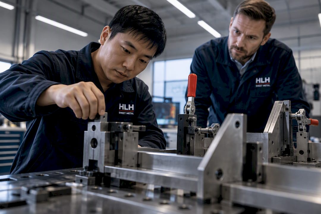
A good weld fixture delivers repeatable, datum-accurate location, clamps a part without deforming it, keeps the joint accessible to the torch or gun, and manages heat so the finished piece holds tolerance. The right amount of fixture complexity scales with production volume: simple clamps and magnets suit prototypes, while dedicated tooling earns its cost through repeatability and throughput on production runs, as explained in Pulse Plating Optimization Services.
TL;DR:
- Fixtures should be designed to ensure location accuracy, clamp stability, heat control, accessibility, and minimal cycle time, with complexity scaling to production volume.
- Materials choices for fixture components depend on application, with steel and cast iron for high volume, and aluminum or stainless steel for weight savings or corrosion resistance.
- Proper locating and clamping strategies prevent distortion by avoiding over-constraining parts and positioning clamps to not interfere with weld access.
- Managing heat via backing bars, interpass timing, thermal breaks, and force-controlled clamping minimizes residual distortion and improves weld quality.
- Regular fixture maintenance, including cleaning, inspecting wear parts, and verification via FEM and test welds, maintains dimensional accuracy over time.
Core Design Principles For Weld Fixtures
Every fixture, whether it costs fifty dollars in shop stock or thousands in machined tooling, has to satisfy the same five objectives. The difference between a prototype jig and a production fixture is how rigorously each objective gets engineered.
- Location accuracy: the part must land in the same position every time, within the tolerance the drawing calls for.
- Clamp stability: clamping force holds the part still without crushing thin sections or pulling it out of true.
- Heat control: the fixture has to absorb or redirect heat so distortion stays predictable.
- Accessibility: locators and clamps cannot block the weld path or filler placement.
- Cycle time: loading and unloading should not become the bottleneck of the welding operation.
The AWS welding handbook frames the decision simply: fixture investment should scale with production volume, and temporary fixturing such as clamps or magnets is cost-effective for small batches, while dedicated fixtures earn their keep on repeat production. A one-off bracket rarely justifies a welded jig. A part running weekly for a year almost always does.
Fixture Components And Common Materials
A typical weld fixture is built from a base plate, locators, clamps, support pads, backing bars, and, where heat buildup is a concern, thermal inserts. Each part has a job: the base plate anchors everything to a known reference, locators fix position, clamps hold it there, and backing bars or copper inserts pull heat away from the joint.
- Base plates: usually mild steel, sometimes cast iron for high-volume tooling that needs enduring flatness.
- Locators and pins: hardened steel or tool steel where wear from repeated loading matters.
- Clamps: steel bodies with replaceable pads to avoid marking finished surfaces.
- Backing bars and heat sinks: copper or aluminum, chosen for thermal conductivity near the weld zone.
- Wear inserts: bushings or replaceable locator tips that keep datum surfaces accurate after many cycles.
A commonly used hole grid spacing on modular fixture plates serves to balance rigidity and tooling reposition flexibility for different part families. Stainless steel components get specified when the fixture itself will see corrosive environments or frequent cleaning, while aluminum shows up where weight matters more than wear resistance.
Locating And Clamping Strategy That Avoids Distortion
The 3-2-1 locating principle is the starting point for almost every fixture: three points define a primary plane, two more fix a second plane, and one final point locks the last degree of freedom. Odd-shaped parts often need creative surfaces for these points (a boss, a machined flat, or a tab added specifically for fixturing) rather than forcing locators onto a curved or uneven face.
- Identify the primary datum surfaces from the drawing before placing a single locator.
- Place the six locating points to fully constrain the part without adding redundant contacts that fight each other.
- Position clamps near, but not on, the weld joint so clamping force does not distort the seam being welded.
- Choose clamp type based on cycle time: quick-action toggle clamps for manual work, screw clamps where higher, controllable force matters.
- Shim as needed to compensate for part-to-part variation before finalizing production tooling.
- Use pads or inserts wherever a clamp contacts a finished or thin surface to avoid marking or crushing it.
Over-constraining a part is a common mistake: extra locators beyond the 3-2-1 count can fight each other as the part heats and expands, introducing the very distortion the fixture was supposed to prevent.
Thermal And Distortion Control During Welding
Clamping force and residual distortion are linked in ways that surprise a lot of engineers. Experimental and modeling work on gas tungsten arc welding found that looser clamping in some cases produced smaller residual deformation than tighter clamping, suggesting that force-controlled fixtures can actively manage distortion rather than simply restraining it. Clamping harder is not automatically better.
Practical controls that work in most shops:
- Backing bars and copper inserts pull heat away from the joint and support the root pass.
- Interpass timing lets sections cool before the next pass adds heat, especially on thicker sections.
- Thermal breaks in the fixture prevent heat from conducting into locators and throwing off later measurements.
- Force-controlled clamping is worth the added complexity on aerospace or medical parts where residual stress has to stay within tight limits.
Pro Tip: Start with the minimum clamp force that holds the part still through tacking, then increase only if the part shifts during welding.
Verifying A Fixture Before Committing To Production
A short verification loop catches problems before they turn into scrapped parts on the floor.
- Run FEM first using realistic clamp boundary conditions and thermal input distribution. Poorly modeled clamp compliance is the single biggest source of error in predicted deformation, according to the IJERT fixture analysis study.
- Tack-fit a sample part in the fixture to confirm locators and clamps actually reach as designed.
- Weld a test coupon and monitor interpass temperature against the plan.
- Measure the part after unclamping, not before, since distortion often reveals itself only once clamping force is removed.
- Iterate on locator position or clamp sequence if measured distortion exceeds the drawing tolerance, rather than adding more clamps.
Practical Shop Examples: Table Thickness And Fixture Layouts
Table thickness and hole pattern decisions come down to expected reaction forces. Heavier welding and larger assemblies call for thicker plate; light sheet metal work does not need it.
- Standard welding tables commonly run from about 0.75 inch to 1 inch of steel plate, with heavier tooling favoring the thicker end of that range.
- A 5/8-inch hole grid is a common modular standard, letting the same table accept different locator and clamp layouts across projects.
- Quick tack fixture example: a flat steel base plate, three fixed pins, one adjustable stop, and two toggle clamps, built for a one-off or short prototype run.
- Dedicated production fixture example: a machined base plate, hardened wear-insert locators, copper backing bar under the joint, and pneumatic clamps sequenced to match the weld path for a part running in volume.
How Iso-certified Fabrication Supports Fixture-driven Production
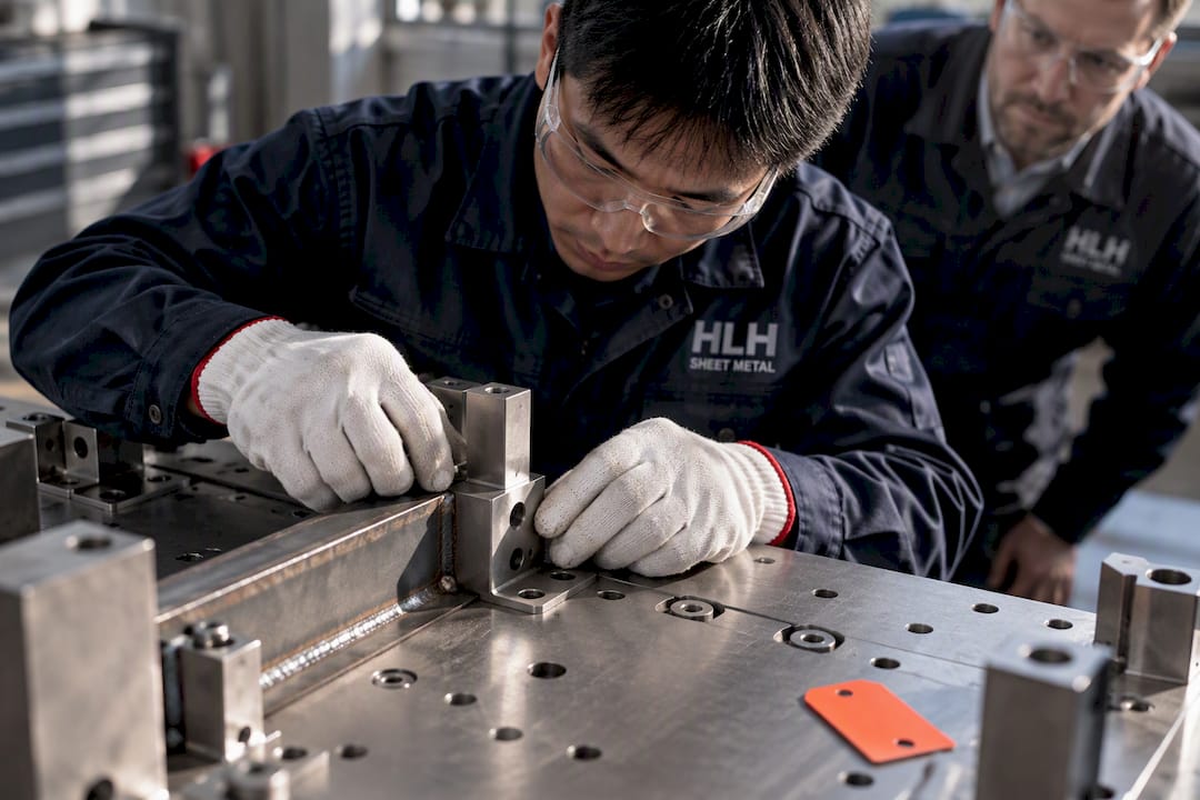
Fixture components need the same dimensional discipline as the parts they hold. Working with an ISO-certified fabricator that can machine base plates, cut locators, and weld backing bars to spec reduces the iteration cycle between a fixture design and a working jig on the floor. It matters most when volume, tight tolerances, or unusual materials make in-house tooling impractical.
Safety Considerations In Weld Fixture Design
Fixtures that hold parts securely also have to keep operators safe around moving clamps, hot surfaces, and welding arcs. A clamp that releases unexpectedly under load is a hazard the design has to eliminate, not just minimize.
- Guard pinch points on toggle clamps and screw mechanisms where fingers could get caught during loading.
- Ground the fixture properly so welding current has a controlled path and does not arc through bearings or moving parts.
- Insulate or shield hot surfaces on backing bars and heat sinks that stay hot well after the arc goes out.
- Rate clamps for the actual force they will see, with margin, so a clamp does not fail mid-weld.
- Add fume extraction points into the fixture layout itself when the part geometry traps welding fumes near the operator.
Fixtures used with robotic or automated welding cells carry an additional layer of risk: a fixture designed for manual access does not automatically clear a robot’s reach envelope, and interference between the torch, the fixture, and the part has to be checked before the cell ever runs at speed. Fixture reviews should include the same people who will operate or maintain the tooling, since operators often catch pinch points and blind spots that a drawing review misses. Building safety into the fixture at the design stage costs far less than retrofitting guards after an incident.
Cost Optimization Strategies For Weld Fixtures
The AWS scaling rule doubles as the primary cost lever: match fixture complexity to volume rather than over-building for a part that will only run a handful of times. A machined, hardened fixture for a low-volume part wastes budget that would be better spent on the next design iteration.
- Start with modular plates and standard hole grids rather than custom-machined bases, so tooling can be repurposed across projects.
- Reserve hardened wear inserts for high-cycle locators, and use mild steel elsewhere.
- Combine fixtures for part families that share datum surfaces instead of building one fixture per part number.
- Prototype the fixture in low-cost material first (aluminum or even wood for layout checks) before committing to steel.
- Validate with a test coupon before finalizing the design, since fixture rework after production tooling is cut costs far more than an extra design pass.
Cost also shows up in cycle time. A fixture that takes two minutes longer to load than it needs to multiply that cost across every part run for the life of the tooling, so time spent optimizing load and unload sequences on a production fixture usually pays for itself quickly.
Integrating Weld Fixtures With Automation And Robotic Systems
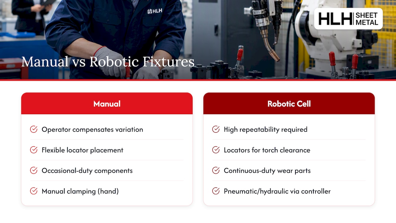
A fixture built for a robotic cell has to solve a different problem than one built for a manual welder. Repeatability matters even more, since the robot has no ability to compensate for a part that lands slightly off position the way a human welder can. Locators and clamps need to be positioned so the robot’s reach and torch angle clear the tooling at every point along the weld path.
Automated cells also tend to run fixtures harder and longer than manual stations, so wear inserts and clamp actuators need to be rated for continuous duty rather than occasional use. Pneumatic or hydraulic clamping is common in robotic cells because it can be triggered directly by the robot controller, removing the operator from the clamping step entirely and tightening cycle time. Datum logic that works well for manual fixturing, locating from a fixed set of reference points rather than from the part’s edges, becomes even more important in automated work, since a robot cannot visually verify that a part is seated correctly the way an operator would.
Maintenance And Durability Of Weld Fixtures
A fixture’s accuracy degrades over time from heat cycling, clamp wear, and the accumulation of weld spatter on locating surfaces. Treating fixture maintenance as a scheduled task rather than a reactive one keeps tolerances from drifting unnoticed.
- Inspect locators and wear inserts on a set interval, replacing them before they wear past the tolerance the fixture was designed to hold.
- Clean spatter from datum surfaces regularly, since a thin buildup on a locating pin shifts part position more than it looks like it would.
- Check clamp force periodically, since springs and pneumatic seals lose performance over thousands of cycles.
- Verify fixture flatness on base plates that see repeated heat cycling, particularly on high-volume production tooling.
- Log fixture performance against part measurements so drift shows up as a trend before it turns into scrapped parts.
Durability starts with material choice, and a base plate or locator specified for the actual duty cycle needs far less mid-life rework than one selected purely on upfront cost.
How I Prioritize Fixture Design Work
Define the tolerance first, try the simplest locators that satisfy it, plan the weld sequence around distortion, then validate with a test coupon before cutting production tooling.
— Nash
HLH Sheet Metal: Services For Fixture Components And Assemblies
Getting fixture components made right the first time saves more engineering time than any amount of redesign after the fact. HLH Sheet Metal fabricates base plates, locators, backing bars, and clamp bodies through sheet metal fabrication services backed by ISO-certified quality checks, with welding services available for assembling fixture frames or validating a design with a welded test coupon before committing to a production run.
Rapid prototyping means a fixture concept can go from drawing to a physical part quickly enough to test locator placement and clamp access before machining a full production version. For engineers weighing whether to build tooling in-house or outsource it, submitting a drawing for a quote is a low-cost way to find out what a properly fabricated fixture actually costs to build.
FAQ
What Are The Different Types Of Welding Fixtures?
Welding fixtures range from simple temporary setups using clamps and magnets, suited to prototypes and low volume, to dedicated modular or hard-tooled fixtures built for MIG, TIG, or spot welding at production volume. The choice depends on part repeatability needs and expected run length, as outlined in AWS fixturing guidance.
What Two Metals Cannot Be Welded Together?
Certain metal combinations, such as aluminum and steel, are difficult to weld directly because of differences in melting point and metallurgical compatibility, and typically require specialized processes or transition materials instead of conventional fusion welding. A qualified welding engineer should confirm compatibility for a specific material pairing before fixture design begins.
What Is The Golden Rule In Welding?
There is no single universally cited “golden rule,” but a consistent theme across fixture and process guidance is controlling heat input and joint preparation to limit distortion and ensure a sound weld. Fixture design supports this by controlling clamping force and heat flow rather than by any single fixed rule.
How Thick Should A Welding Fixture Table Be?
Welding fixture tables commonly run from about 0.75 inch to 1 inch of steel plate, with thickness scaling up for heavier assemblies and stronger welding reaction forces. Lighter sheet metal work can use thinner tops, but a 5/8-inch hole grid remains a common standard for modular tooling regardless of plate thickness.
When Should I Use A Dedicated Fixture Instead Of Temporary Clamping?
A dedicated fixture becomes worthwhile once a part runs repeatedly and tolerance or throughput requirements exceed what manual clamps and magnets can reliably deliver. The AWS handbook frames this as scaling fixture investment directly to production volume.

