




Table Of Contents
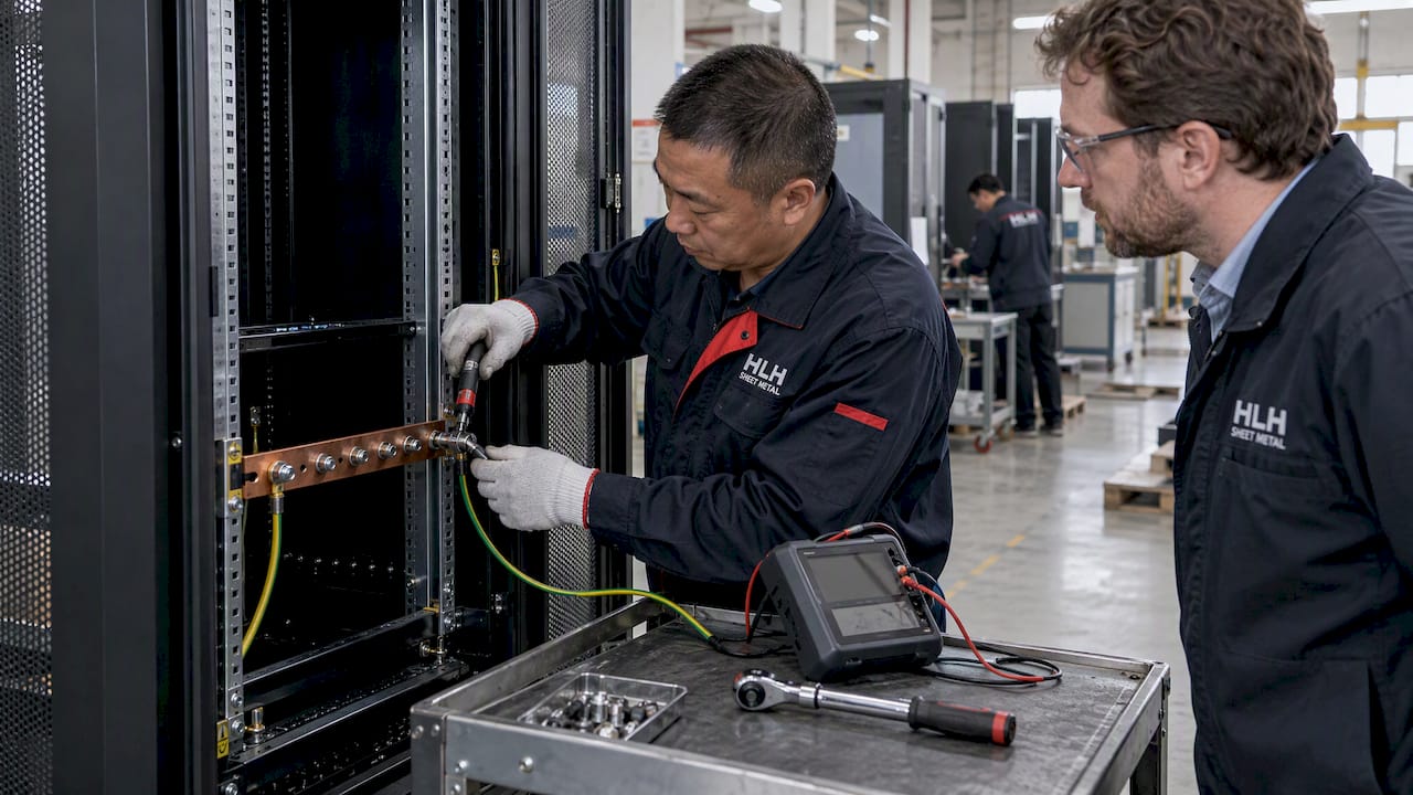
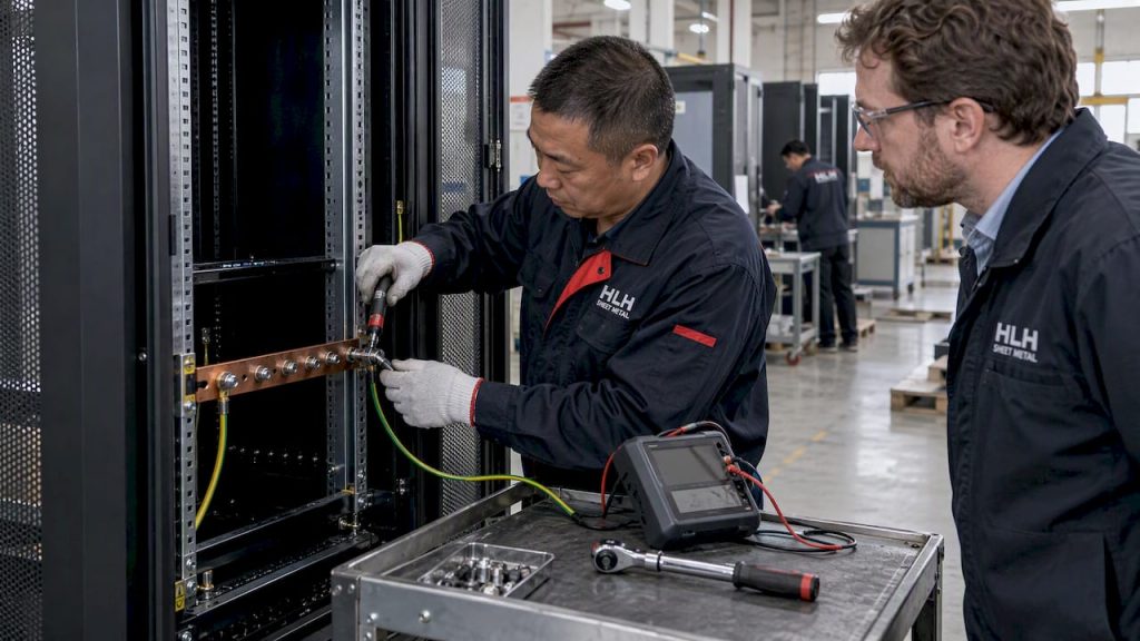
Server rack grounding, in manufacturing terms, means the grounding studs, busbars, and bonding hardware built into a cabinet at the factory, not field wiring added after delivery. The single demand that should appear in every RFQ is that each cabinet ships with its own direct, tested connection to the telecommunications bonding backbone, sized to recognized standards and verified before it leaves the plant. Some suppliers build these features into custom cabinets rather than leaving them to on-site improvisation.
TL;DR:
- Each server cabinet should have factory-installed bonding provisions, including bonded studs, busbars, and contact pads, verified before shipment.
- The bonding conductor connecting the rack to the telecommunications bonding backbone must be at least 6 AWG and directly terminated, not daisy-chained via power cords.
- Factory-verified contact resistance for bonding points should be 0.1 milli-ohms or less, with corrosion controls to prevent galvanic corrosion for long-term reliability.
- Procurement must reference standards like NECA/BICSI 607 and specify hardware, sizing, torque, and testing requirements in RFQs to ensure consistent grounding quality.
- Regular maintenance, including visual inspections and low-ohm continuity tests, is necessary to maintain bonding integrity over the cabinet’s lifespan.
What Factory-integrated Grounding And Bonding Actually Covers
This article is about what a fabricator builds into the cabinet, not how an installer grounds a rack after it arrives on site. That distinction matters because a cabinet with no bonding provisions pushes risk and labor onto the data center team, while a properly specified one arrives ready for a technician to terminate and test in minutes.
Factory-integrated grounding typically includes:
- Grounding studs and two-hole lug pads welded or bonded to the frame
- Horizontal or vertical busbars pre-mounted for unit bonding conductor terminations
- Compression lugs, conductive gaskets, and star washers at removable panels
- Paint removal or plated contact pads at every bonding interface
These elements connect to the telecommunications bonding backbone (TEBC) through a rack bonding conductor (RBC), with the unit bonding conductor (UBC) tying individual equipment to the rack frame. An ISO-certified QA process and prototyping capability allow procurement teams to verify these features on a sample unit before committing to a production run.
Key Standards And Normative Specs Procurement Must Reference
Grounding requirements for telecommunications and data center cabinets are not guesswork. They come from a small set of standards that procurement should cite directly in specifications rather than paraphrase.
The most relevant references are:
- NECA/BICSI 607 guidance on telecommunications bonding and grounding
- The IEC 60364 family and HD 60364-5-54 for electrical installation bonding
- EN 50310 for telecommunications bonding infrastructure in buildings
- EN 61539 and ISO/IEC 22237 or EN 50600 where data center facility design applies
NECA/BICSI guidance specifies that the TEBC must be a continuous copper conductor sized no less than 6 AWG, or sized to match the largest equipment grounding conductor in the AC branch circuits, and that cabinets must bond to it directly rather than through daisy-chained power cords. This single clause, cited verbatim in an RFQ referencing NECA-BICSI 607, eliminates most ambiguity about conductor sizing and termination method.
When writing an RFQ, reference the clause number alongside the requirement rather than a general statement like “grounded per industry standard.” A vendor quoting against “TEBC per NECA-BICSI 607, 6 AWG minimum, direct RBC termination” has no room to substitute an undersized or shared conductor.
Manufactured Grounding Features And Recommended Hardware
A grounding-ready cabinet carries specific hardware, not generic metal contact. Engineers writing a bill of materials should specify each item rather than leaving hardware selection to the shop floor.
Core components to call out:
- Grounding studs or two-hole lug pads sized to the expected conductor gauge
- Pre-mounted horizontal or vertical busbars for multiple unit bonding conductor terminations
- Bonding jumpers across hinges and removable panels, using conductive gaskets or star washers
- NRTL-listed compression lugs, torqued to the supplier’s spec, with color-coded or marked bonding points
Removable doors and side panels are often bonded with a flexible jumper in the 12 AWG range with a quick-connect fitting, which lets technicians detach a panel without breaking the ground path permanently. Where electromagnetic interference control matters more than general safety bonding, flat braid straps replace round conductors because they offer lower impedance at higher frequencies.
Pro Tip: Specify paint removal or a plated contact pad at every bonding interface in the drawing package, not just in a general note, so the fabricator cannot interpret “clean contact surface” loosely.
RBC And TEBC Sizing, Contact Resistance, And Corrosion Control
Numbers are what separate a spec a vendor can be held to from one they can argue with. The Legrand bonding and earthing white paper gives concrete minima that procurement can paste directly into a technical specification.
| Parameter | Value |
|---|---|
| RBC minimum, cabinets ≤21U | 4 mm² |
| RBC minimum, cabinets >21U | 16 mm² |
| TEBC conductor sizing | No less than 6 AWG, or equal to largest branch-circuit equipment grounding conductor |
| D.C. contact resistance, bonding connectors | 0.1 mΩ or less |
| Mating-surface electrochemical potential | 300 mV or less |
The Legrand white paper states that bonding connectors and fastenings must be designed to maintain a d.c. contact resistance of 0.1 mΩ or less, with mating surfaces kept to an electrochemical potential difference of 300 mV or less. These two numbers give procurement an objective pass or fail line for factory test reports rather than a subjective “looks properly grounded” sign-off.
Material selection drives whether those numbers hold up over years of service. Mixing dissimilar metals at a bonding joint sets up galvanic corrosion that raises contact resistance over time, so matched metals, plating, or an antioxidant compound at the joint belong in the spec alongside the resistance target. HLH Sheet Metal’s surface finishing services cover plating options that address this directly, and a closer look at galvanic corrosion controls is worth a read for anyone specifying mixed-metal enclosures.
Integration And Factory QA Checks To Demand
A grounding spec is only as good as the test records behind it. Procurement should require documented proof that every bonding point meets the numeric targets before the cabinet ships.
- Continuity testing with a low-ohm meter at every bonding point, with readings recorded against the 0.1 mΩ threshold.
- Torque verification on every grounding lug, logged against the supplier’s torque spec.
- Visual confirmation of paint removal or plated contact prep at each bonding interface.
- Verification that installed lugs carry NRTL listing matched to conductor gauge.
- Delivery of test reports, as-built grounding drawings, and photos of each bonding point alongside the shipment.
Packaging matters too. Contact surfaces that arrive scratched or re-coated in transit protection film need rework on site, so handling instructions that protect bonding pads during shipping belong in the purchase order, not as an afterthought.
Rfq-ready Checklist And Sample Clauses Procurement Can Paste
An RFQ that states requirements in plain prose invites interpretation. One that cites clause numbers and numeric thresholds does not.
- Cite the standard and clause directly: “TEBC and RBC per NECA-BICSI 607, section on telecommunications bonding backbone connections.”
- State the no-daisy-chain rule explicitly: each cabinet terminates its own RBC to the TEBC, independent of adjacent cabinets.
- Specify RBC sizing by rack height, following the 4 mm² and 16 mm² thresholds above.
- Set the d.c. contact resistance ceiling at 0.1 mΩ and require it in the test report.
- Require NRTL-listed compression lugs sized to conductor gauge, with manufacturer part numbers disclosed.
- Require a prototype or first-article sample for continuity and torque verification before production release.
- Define the remedy for nonconformance: rework, replacement, or credit, agreed before the purchase order is signed.
A prototype approval step catches a sizing or hardware mismatch on one unit instead of a full production run, which is the entire point of requiring it before tooling commits to volume.
Effects Of Improper Grounding On Server Performance And Electromagnetic Interference Issues
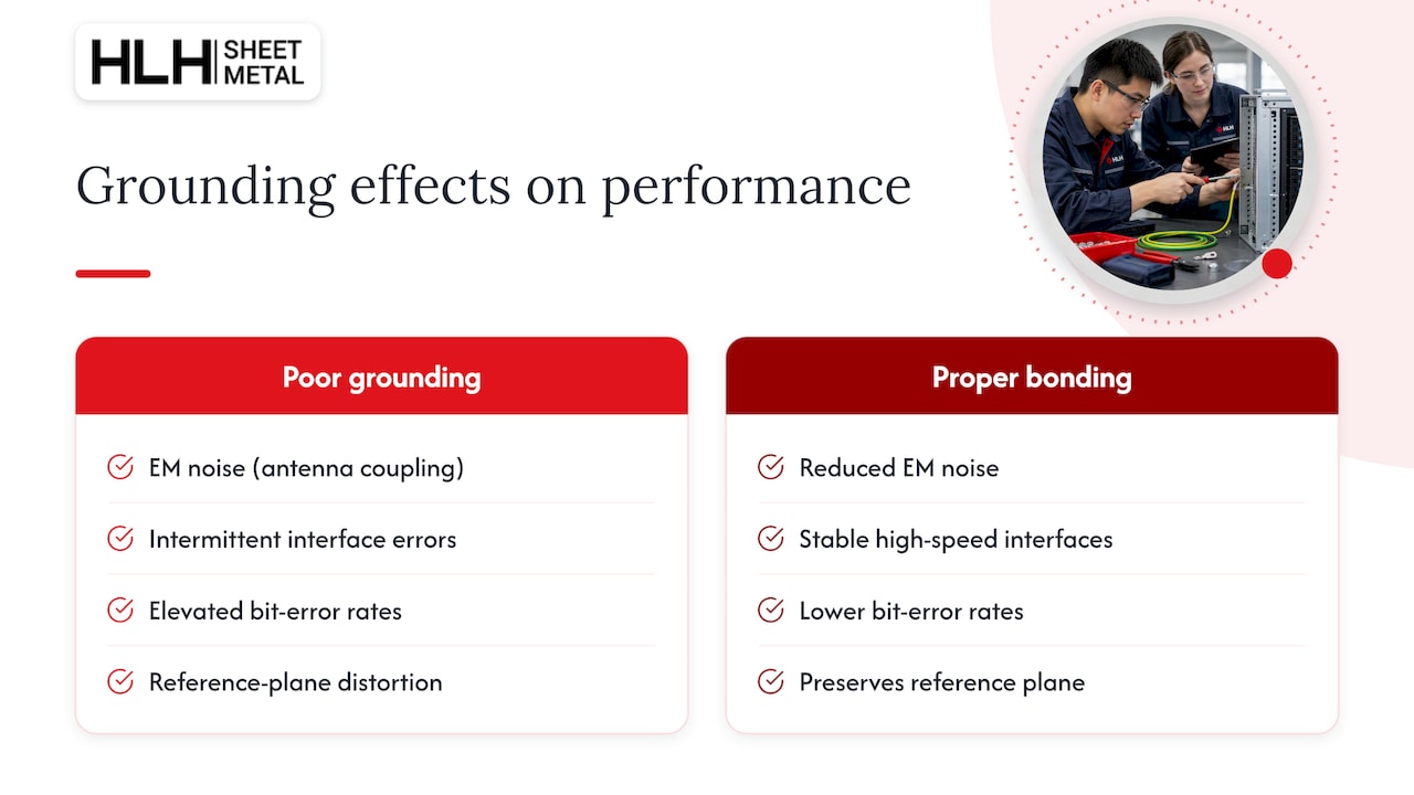
A cabinet with inconsistent or undersized bonding does not just fail a safety inspection. It introduces electrical noise that degrades the equipment it houses. When a chassis panel or rail is only loosely bonded, or when paint is left under a lug instead of removed, the resulting high-impedance joint acts as an unintended antenna, radiating or coupling noise into nearby signal paths.
This shows up as intermittent errors on high-speed interfaces, elevated bit error rates on fiber or copper links near the affected panel, or noise on sensitive measurement and control equipment sharing the same enclosure. In mixed-signal environments, a poorly bonded rack can also distort the reference plane that shielded cabling and connectors depend on, undermining the shielding effectiveness those components were chosen to provide in the first place.
Fault conditions compound the problem. A ground path with high resistance will not clear a fault quickly, which can let voltage rise across the chassis and its connected equipment for longer than intended, with extended exposure for anything plugged into that cabinet during the fault. A low-impedance path, by contrast, directs fault current away quickly and keeps touch voltage within safe limits.
None of this requires exotic hardware to prevent. It requires every bonding joint, from the frame to the rail to the unit bonding conductor, to meet the same contact resistance target consistently, rather than relying on paint contact or a single ground strap to carry the entire cabinet’s return path.
Maintenance And Inspection Schedules For Grounding System Integrity Over Time
Grounding hardware does not stay compliant forever once installed. Vibration from cooling fans, thermal cycling, and routine maintenance work on cabinets all loosen fasteners and degrade contact surfaces gradually.
An annual visual inspection of accessible bonding points, checking for corrosion, loose lugs, or damaged jumpers, catches most degradation before it affects performance. A continuity check with a low-ohm meter on a sampling of bonding points, compared against the original factory test record, confirms the resistance values have not drifted upward.
Any time a panel, rail, or piece of equipment is removed and reinstalled, the bonding jumper or UBC connection for that component deserves a quick continuity check rather than an assumption that reassembly restored the original contact. Torque on accessible grounding lugs is worth rechecking on the same cycle, since thermal expansion and contraction can loosen a fastener that was correctly torqued at installation.
Facilities with environmental extremes, high humidity, coastal corrosion exposure, or heavy vibration from adjacent mechanical equipment warrant a shorter inspection interval than a climate-controlled interior data hall. Keeping the original factory test report on file gives the maintenance team a baseline to compare against, rather than guessing whether a measured value represents drift or was always on the high side.
Common Grounding System Topologies And Their Pros And Cons
Two topologies dominate telecommunications and data center grounding: single-point and multipoint (mesh).
A single-point topology ties every rack and piece of equipment back to one central grounding reference, typically the TEBC or a main grounding busbar, through its own RBC. This keeps the ground path predictable and avoids ground loops between racks, which makes it the default recommendation in most telecommunications bonding guidance. Its main limitation is scale: in a large facility with many rows, conductor lengths back to a single point grow long, and every cabinet still needs its own dedicated run rather than sharing a conductor with a neighbor.
A multipoint or mesh topology bonds equipment to a common grounding grid at multiple points, which is common in facilities handling high-frequency signals where a single long conductor back to one point would itself introduce impedance. This approach shortens the path from any given rack to a ground reference but requires more careful design to avoid unintended loops between the multiple connection points.
For most server rack cabinets, the practical answer is a single-point topology at the rack level: each cabinet gets its own RBC to the TEBC, satisfying the no-daisy-chain requirement, while the broader room may use a mesh grounding grid that the TEBC itself connects into. The cabinet manufacturer’s job is the first half of that chain: a clean, dedicated bonding point ready to terminate, regardless of which room-level topology the facility ultimately uses.
How Rack Grounding Fits Into The Data Center Earthing System
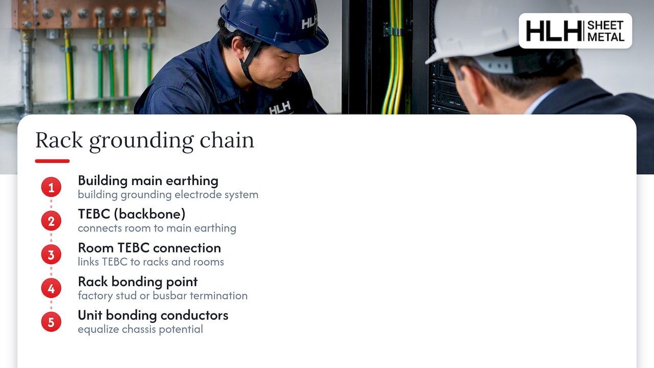
A cabinet’s grounding hardware is only the last link in a longer chain that starts at the building’s main earthing system and runs through the telecommunications bonding backbone to every rack in the room. Getting the cabinet right does not substitute for getting the rest of that chain right, and getting the rest of that chain right does not help if the cabinet itself has no proper termination point.
Electrical safety in this context has two separate jobs: protecting people from shock hazards during a fault, and protecting equipment from damage and noise during normal operation. The RBC and TEBC connection primarily serves the safety function, giving fault current a low-impedance path back to the source so protective devices trip quickly. The unit bonding conductors and busbars inside the cabinet handle the equipment-level function, keeping every chassis at the same reference potential so a fault on one unit does not energize the frame of its neighbor.
Facility design standards such as ISO/IEC 22237 and EN 50600 address the room-level earthing system, including how the TEBC itself connects to the building’s main grounding electrode. A cabinet manufacturer does not control that part of the chain, but a cabinet with no clear, standards-referenced bonding point forces facility electricians to improvise a connection on site, often with less precision than a factory-installed stud or busbar provides. Specifying the cabinet’s grounding features to the same standards the facility’s earthing system already follows is what keeps the two halves of that chain compatible rather than mismatched.
Installing And Verifying Grounding Connections Step By Step
Once a grounding-ready cabinet arrives on site, the installation sequence is straightforward if the factory work was done correctly. The RBC terminates from the cabinet’s grounding stud or busbar to the TEBC, using an irreversible compression lug sized to the conductor gauge specified in the cabinet’s documentation. Each individual piece of rack-mounted equipment then bonds to the rack frame or busbar through its own UBC, rather than relying on the equipment’s power cord ground alone.
Verification starts with a visual check: confirming the RBC is present, terminated at both ends, and routed without sharp bends or compression damage. A continuity test with a low-ohm meter follows, measuring resistance from the equipment chassis through the UBC and RBC to the TEBC, and comparing the reading against the 0.1 mΩ target established at the factory.
Torque on every accessible lug should be checked against the lug manufacturer’s spec, since an under-torqued connection can pass an initial continuity test but degrade within months as the joint loosens. Any bonding point where paint or coating was not fully removed at the contact surface should be flagged and corrected before the cabinet goes into service, since that one weak point can undermine an otherwise correctly bonded cabinet. Recording these verification results against the as-built grounding drawing supplied with the cabinet gives the facility a baseline for future maintenance checks.
Manufacturing Perspective: Why Integrated Grounding Reduces Risk And Rework
Welded, integral bonding points cost more up front but remove a failure mode entirely: there is no bolted joint to loosen or repaint over. Bolted connections with tested, listed hardware are the practical middle ground for most cabinets, provided the torque and resistance values are verified at the factory rather than assumed from the hardware spec sheet. HLH Sheet Metal’s prototyping process lets a design team confirm those values on a single unit before committing to a production run, which is the cheapest place to catch a sizing mistake.
— Nash
HLH Sheet Metal: How We Deliver Grounding-ready Server Racks
HLH Sheet Metal builds grounding and bonding features into custom server rack cabinets as part of the fabrication process, backed by ISO-certified quality control and a prototyping step that lets you verify contact resistance and hardware fit before full production. Multiple manufacturing plants and an English-speaking support team mean a procurement team anywhere can get a sample unit tested and a production run scheduled without managing the process across a language gap. If your next cabinet order needs grounding studs, busbars, and tested bonding points built in from the start, start with our sheet metal fabrication capabilities page and request a quote for your specification.
FAQ
What Does Server Rack Grounding Mean For A Fabricated Cabinet?
It refers to the grounding studs, busbars, and bonding hardware a manufacturer builds into the cabinet frame, not field wiring added after installation. These factory features give the installer a direct, tested point to terminate the rack bonding conductor to the telecommunications bonding backbone.
Why Can’t Adjacent Racks Share One Ground Connection?
Daisy-chaining racks creates a single point of failure: removing or disconnecting one cabinet can break the ground path for every cabinet downstream of it. The NECA-BICSI 607 guidance calls for each cabinet to have its own direct connection to the TEBC instead.
What Contact Resistance Should A Bonding Connection Meet?
Bonding connectors and fastenings should maintain a d.c. contact resistance of 0.1 mΩ or less, per the Legrand bonding and earthing white paper. This figure gives procurement an objective threshold to require in factory test reports.
How Is The RBC Sized For Different Cabinet Heights?
The same white paper lists a minimum of 4 mm² for cabinets of 21U or less and 16 mm² for cabinets taller than 21U. Procurement should specify the applicable size in the RFQ based on the cabinet’s rack unit count.
Do Some Manufacturers Build Grounding Features Into Custom Cabinets?
Yes, some fabricators manufacture custom server rack cabinets with grounding studs, busbars, and bonded contact points as part of their sheet metal fabrication services, supported by ISO-certified QA and prototyping. Specific hardware and sizing are typically confirmed per project specifications during the quoting process.
Primary Standards And White Papers To Consult
The NECA-BICSI 607 guidance and the Legrand bonding and earthing white paper are the two primary references behind the standards and numeric targets in this guide. For design-stage context, see HLH Sheet Metal’s notes on rack dimensional standards and EVT-reducing cabinet design.

